Ok, avoiding the fuses and flasher deal itself what it looks you already did it here are my thoughs
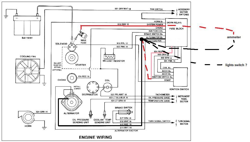
as you can see on my diagram, the discontinued lines represents the Mopar wiring method
but then some doubts comes into my mind...
what source feeds the wire I outlined in pink to ign switch ? RED FROM STARTER OR BLACK FROM ALTERNATOR connected in to the fuse box ?
what about the LIGHT SWICTH SOURCE ? where comes from ? The POWER SYSTEM WIRE OR THE ALTERNATOR WIRE ON FUSE BOX ? instruction sheet on point 12 states:
12. ATTACH THE WIRE TO POWER UP THE HEAD LIGHT SWITCH TO THE LIGHT
SW B+ TERMINAL. (RED W/ BLACK STRIPE WIRE) (12GA) but doesn't say whats the input source to feed it... power system or alternator wire
BOTH OF THOSE WIRES ARE spliced in to the alt wire on stock system to use ammeter correctly, but dunno what does feed the POWER SYSTEM WIRE into the painless fusebox.
when I know what feeds this wire into the new fuse box will be able to diagram how to wire it.
To be able to use correctly the ammeter all the load needs to be on black wire side of the ammeter
still analizing
( BTW, dunno why 2 acc wires coming from ign switch on diagram )
BASICALLY all my doubts are concerned into:
-on painless fusebox, What is the source what feeds the ign switch and the lights switch... Alt wire or Power system wire ?
-on painless fusebox, What is the source what feeds all the constant powered fuses/devices ? Alt wire or Power system wire ?
without having the fuse box in hands or without known the Chebby system ( what it looks Painless is based ), is hard to tell to me
Can you check for continuity to know what wires/circuits register continuity with ALT wire and wich ones with SYSTEM POWER wire ?


