Part 2-T&D 1.7 ratio rocker arms. Part number 8013, 5/8” shaft, paired rockers per cylinder. Component Observations
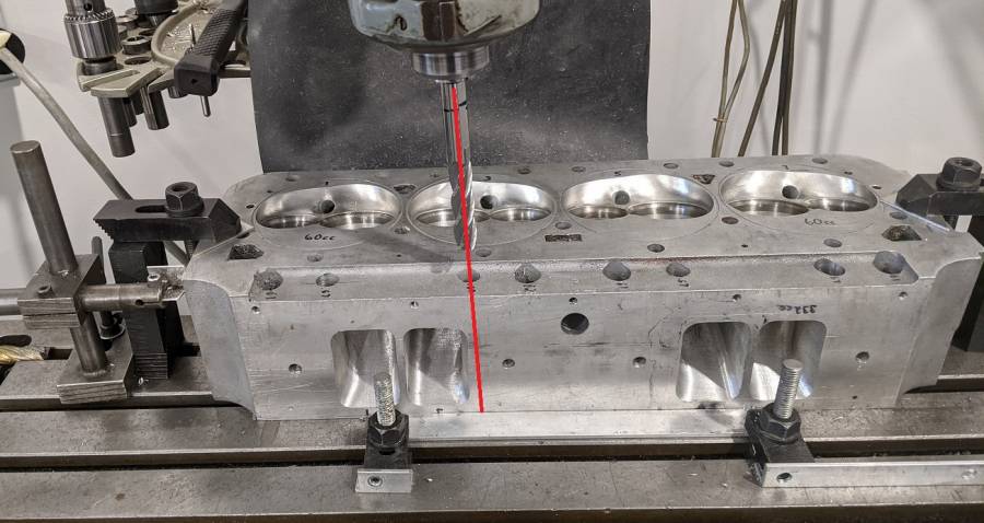
The T&D 1.7 ratio rocker part number 8013, 5/8” shaft, paired rockers per cylinder will require elongating the pushrod holes in the heads toward the intake manifold side. The T&D catalog shows the #8013 set uses 0.080” longer rocker arms than the typical B1 single shaft per head setup. So that explains the holes needing to move toward the intake manifold, away from the valve side of the heads. And my first mock-up shows the holes do need that work, especially the intake pushrod holes. I used a 5/8” dia endmill and moved the centerline 0.125” toward the intake manifold side. The heads originally had a 5/8” dia hole for the intake pushrod, and a 3/4” dia hole for the exhaust pushrod. So moving the centerline of the larger exhaust hole with the 5/8” endmill had less affect than the intake holes.
Note, the intake pushrod holes are at an angle to allow the wider B1 intake port and the 0.800” offset rocker arms. Also, the 0.125” move is more important at the top, rocker end, since the pushrod will angle back to the same lifter location.
During Part 4 Mock ups, most of the intake holes needed another 0.010” near the top. Since the final/actual lifter location on the base circle, and the final pushrod length, required turning the rocker adjusters about 1.5 turns from the factory supplied position (which was screwed all the way in, i.e. minimum cup sticking out.) My final clearance work in Part 4 changes the Part 2 distance “0.125 inch” to “0.145 inch”.

Last edited by 440Jim; 09/18/21 12:34 PM. Reason: Added Part 4 need for more clearance.

