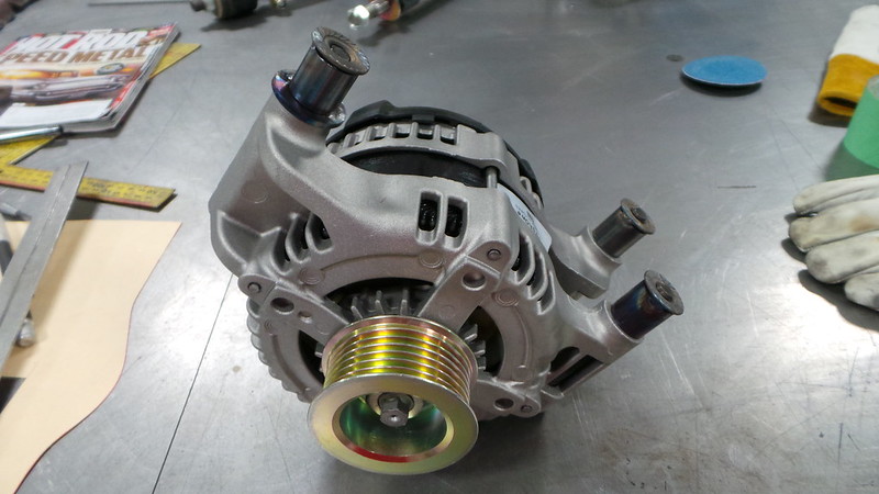
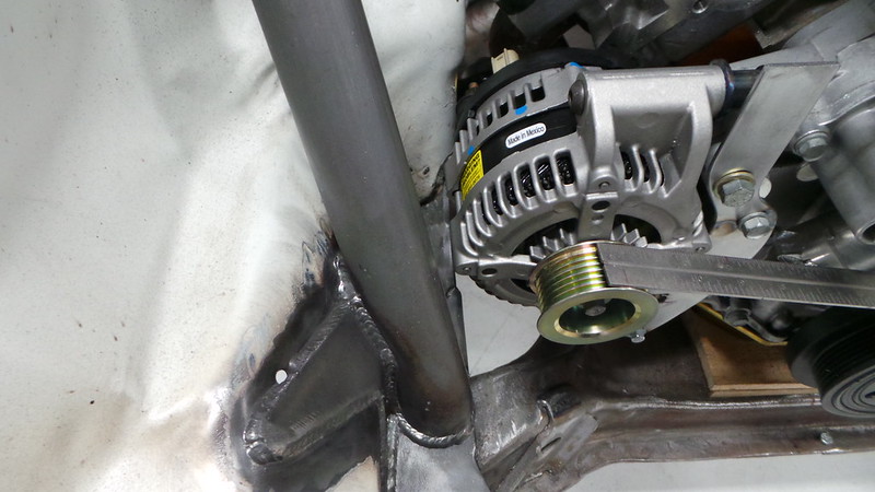
One of trickiest parts about swapping an engine from one vehicle into another is getting all of the engine accessories to clear all of the sheet metal of the new vehicle's engine bay. After we swapped the modern 392 HEMI into our Project '76 Dart, we found that the factory alternator was just too big to fit without some serious modification to the car. Luckily, there was a better option than modifying the car to fit the alternator - finding an alternator to fit the car! The reason we could do this is because the factory alternator that came with the engine was designed to put out a lot of amperage to be able to support a modern vehicle's massive electronic system. Because this was going into a race car with minimal electronics we could utilize a smaller alternator that generated less amps, but we had to design an all new mounting bracket for it.
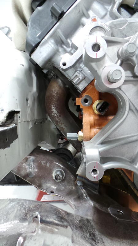
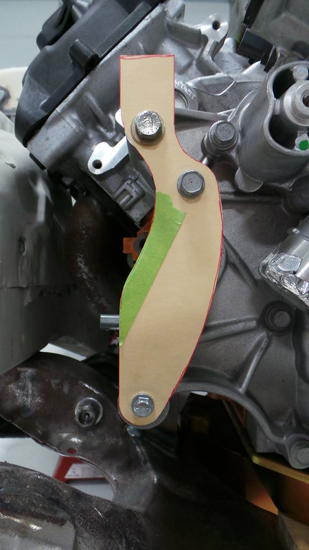
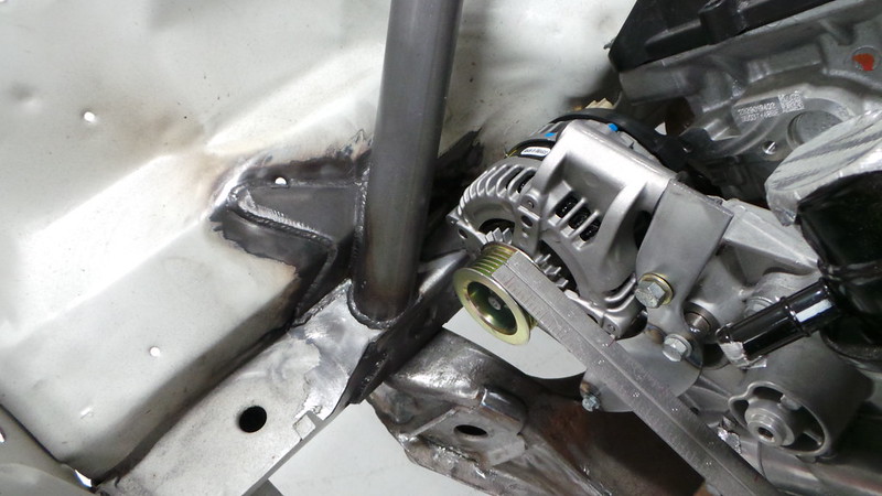
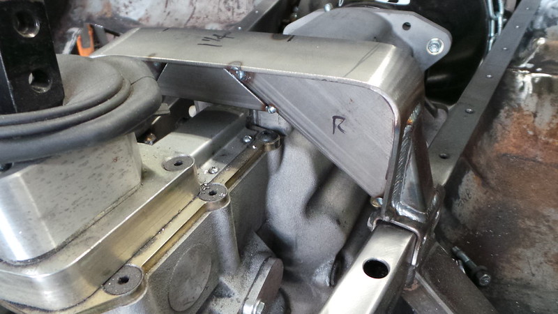
After selecting the new alternator, we set out looking at the available mounting holes in the block to determine the design of the new bracket. We needed to be able to move the alternator up to clear the chassis and forward to bring the pulley into alignment. Once we measured the location of the mounting holes we were able to make our initial design of the bracket out of cardboard to verify clearance and make the final adjustments to the design.
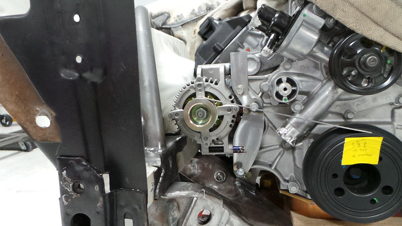
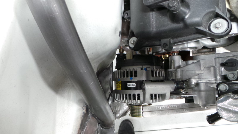
The next step in the process was to create a temporary metal bracket that we would use to really fine tune the alternator's position to ensure proper belt alignment before we fabricate the final version of the bracket.
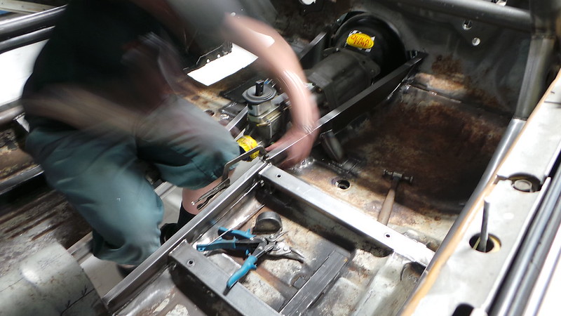
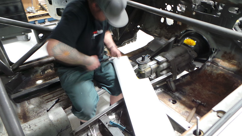
The design requirement of the transmission tunnel on Project '76 Dart was much different than what most people are used to seeing. Because of the types of racing that Kevin will be doing, he asked that the front half of the tunnel be removable so that the transmission can be serviced and removed through the tunnel itself - much like in professional rally cars.
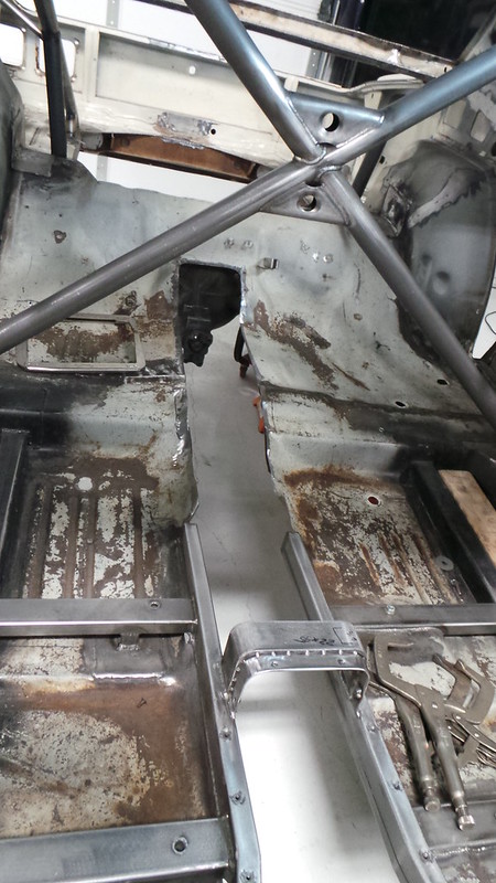
The first step of the process was to create the frame of the transmission tunnel. This framework was also tied into the safety cage through the supports rails for the racing buckets.
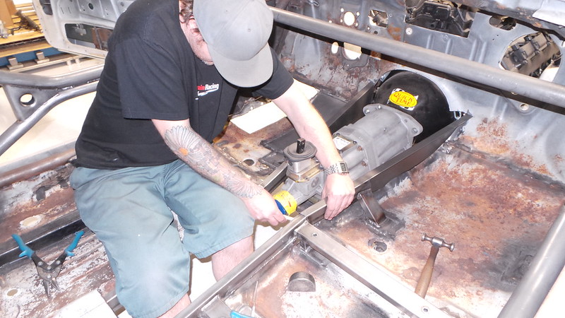
The next step was to construct the transmission tunnel support hoops which included both a removable hoop over the transmission as well as an integrated drive shaft safety hoop just aft of the front driveshaft yoke.
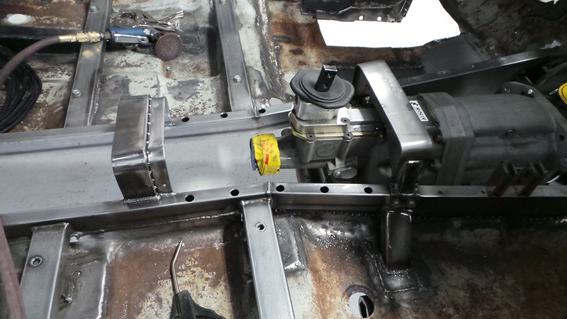
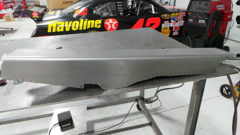
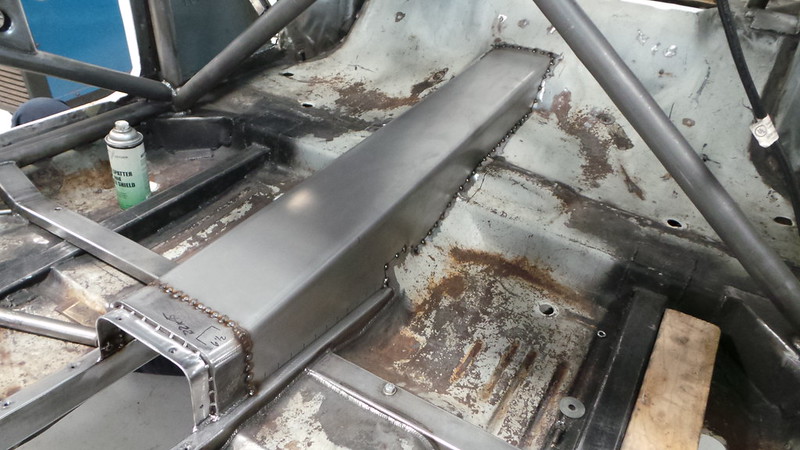
Now that all of the support hoops were in place, we were able to move forward with fabricating the skin of the tunnel itself. The permanent rear section of the tunnel was the first to be completed. After creating patterns to match the contour of the floor pan, we sketched out the locations for the tack welds onto the finished piece and secured it into place.
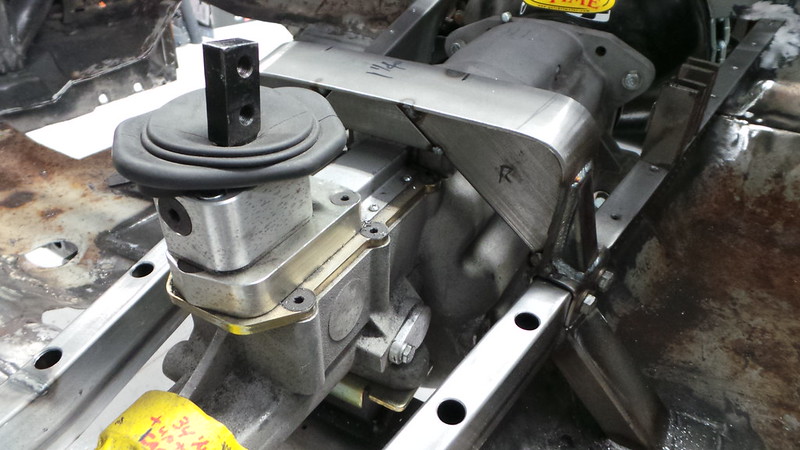
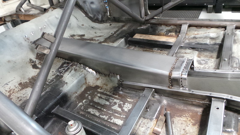
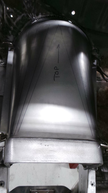
Next it was on to the first removable section which covers most of the transmission. The sheet metal was bent into shape and structural tack weld points were identified before the new piece was secured onto the front and rear brackets.
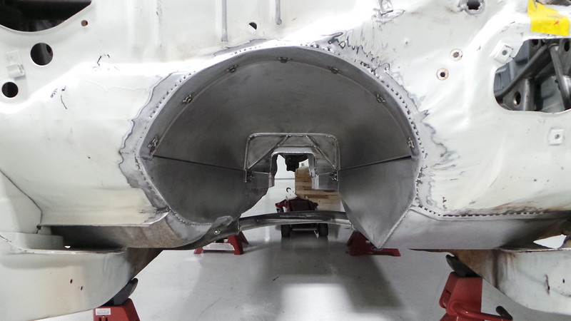
Here is the view down the mostly complete transmission tunnel. More updates to come soon.