Reducing voltage drop in Ignition/alternator curcuit
#425022
Reducing voltage drop in Ignition/alternator curcuit
#425022
07/31/09 07:56 PM
07/31/09 07:56 PM
|
Joined: Jan 2003
Posts: 1,482
Lake Orion, MI
goldduster318
 OP
OP
pro stock
|
OP
pro stock
Joined: Jan 2003
Posts: 1,482
Lake Orion, MI
|
After replacing my alternator today due to overcharging (was getting 18V on the gauge in the car) because of continuity to ground between the case and field terminals, I decided I would look more closely at the electrical system.
The Autometer gauge in my dash typically shows about 14.5, which I figured was normal, and is steady. When I check the voltage at the back of the alternator, I get 15.3 when the volt gauge on the dash is at 14.5.
So, next, I checked the voltage at the blue wire at the alternator under the same scenario. It showed 14.53V. This makes me think that the voltage regulator is trying to regulate to 14.5V.
My next step was to shut the car off and check the battery voltage, and the voltage feed from the battery to the ignition switch. The battery was showing 12.5V and I was getting 12.4V at the battery feed at the ignition switch.
I also checked the resistance across the ignition switch...its zero. This leads me to think that when higher current flows through the bulkhead connector, that there is a voltage drop.
My volt gauge reads 14.5V because this car has the "MAD Electical" amp gauge bypass....and why I have full battery voltage at the B+ lead.
What is a good way to fix this? The bulkhead terminals look pretty clean making me think that I need to use a relay for the ignition 2, which would provide the reference voltage to the back of the alternator as well as the power to the voltage regulator, coil, and ignition box.
The problem is that I'm not sure that a 30amp relay would be enough for this applicaition, and I'm also not sure what size fuse I would need.
Anyone have any experience/ideas?
Last edited by goldduster318; 07/31/09 10:03 PM.
'70 Duster 470hp 340/T56 Magnum/8 3/4 3.23 Sure-Grip
|
|
|
Re: Reducing voltage drop in Ignition/alternator curcuit
[Re: goldduster318]
#425024
07/31/09 11:31 PM
07/31/09 11:31 PM
|
Anonymous
Unregistered
|
Anonymous
Unregistered
|
So far you haven't proved there's a problem. What you want is to use an accurate multimeter AT THE BATTERY and see if it's in reason say, 13.5-14.5, and then see if maybe the main fusebox is in reason--it'll be a little different.
Now do this, with the engine simulating low/med cruse (1500-2000rpm) check with accessories off, and then with them on, say headlights and heater blower
Stab a probe directly onto the battery neg. and the other directly onto the regulator mounting.
Next stab a probe directly onto the battery pos and the other at the reg. ign term.
IN BOTH CASES you want as low as readings as possible, two tenths of a volt or so would be good, much higher bad, and something approaching .4-.5V (1/2 volt) unacceptable. These two readings show the voltage drop in your ground PATH all the way from the batt to the regulator mount.
Same deal with the pos. reading, shows the drop across the entire harness from the battery, the cable(s) connections/ harness/ bulkhead/ ign switch/ ammeter etc etc and all the way out to the regulator ign terminal.
If the reading at the alternator stud is very high, let's say 17, all that shows is that there's some drop on the harness from the alternator CHARGING WIRE which can be quite long unless you've bypassed it directly (bypassed the ammeter) THIS DROP does not affect much UNLESS it shows up at places like the fuse feed, etc.
|
|
|
Re: Reducing voltage drop in Ignition/alternator curcuit
#425025
08/01/09 10:12 AM
08/01/09 10:12 AM
|
Joined: Jan 2003
Posts: 1,482
Lake Orion, MI
goldduster318
OP
pro stock
|
OP
pro stock
Joined: Jan 2003
Posts: 1,482
Lake Orion, MI
|
I should have been more clear. The voltage at the battery exactly the same as it is at the alternator within 0.04V. The charging path that goes through the dash harness and ammeter has been bypassed. So, there is a 10 GA wire from the alternator B+ terminal to the starter relay B+ terminal. Then, there is a connection from the starter relay B+ terminal that bypasses the bulkhead connector, uses twin 10 GA wires, and then connects to the main splice behind the gauge cluster.
So basically, across the battery I get 15.3V and at the field terminal on the alternator, I get 14.53V, which is also pretty much what I get on the dash mounted volt gauge.
I will have to check the fusebox reading and also the reading at the ignition switch feed while running.
'70 Duster 470hp 340/T56 Magnum/8 3/4 3.23 Sure-Grip
|
|
|
Re: Reducing voltage drop in Ignition/alternator curcuit
[Re: goldduster318]
#425026
08/01/09 10:33 AM
08/01/09 10:33 AM
|
Joined: Jan 2003
Posts: 1,482
Lake Orion, MI
goldduster318
OP
pro stock
|
OP
pro stock
Joined: Jan 2003
Posts: 1,482
Lake Orion, MI
|
Quick check with the engine off, key in "run" position:
Across Battery: 12.16V
B+ Stud on back of Alt: 12.15V
Fuse Box 11.77V
Ignition Switch B+ Feed: 11.9V
Ignition 1 Feed out of Ignition Switch 11.70V
Ballast Resistor Feed (IGN1): 10.94V
Alternator Field Wire: 10.86V
Battery Neg to Regulator Power Feed (blue wire): 11.60V
Battery Neg to Regulator case: 0.03V
'70 Duster 470hp 340/T56 Magnum/8 3/4 3.23 Sure-Grip
|
|
|
Re: Reducing voltage drop in Ignition/alternator curcuit
[Re: goldduster318]
#425027
08/01/09 12:11 PM
08/01/09 12:11 PM
|
Anonymous
Unregistered
|
Anonymous
Unregistered
|
You can't check this way with the engine off. Voltage drop across a harness is caused by CURRENT FLOW and RESISTANCE.
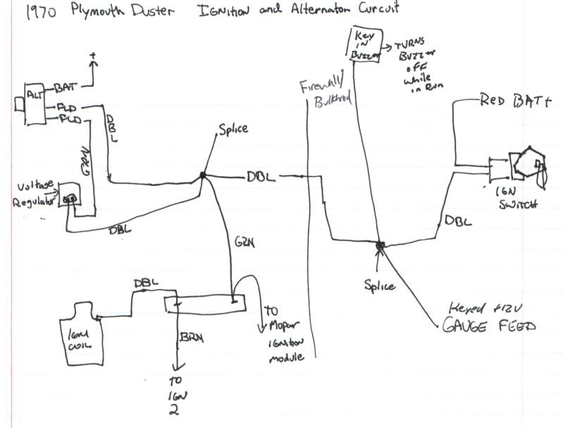
The resistance can be anywhere and everywhere, you have to find it. It can be too small wire, wire with some strands broken, poor/ corroded crimps at the wire ends, poor/ loose/ corroded blades in the connectors (bulkhead, others) and the connector RIGHT AT the ign switch as will as the contacts IN the switch itself. Get yourself a diagram and lay it all out. ALL resistance adds up. Probably your no.1 suspect is still the bulkhead connector BUT BUT many (most? all?) of these cars have a welded splice or two IN THE UNDER DASH HARNESS and I've fixed THREE of these in cars "back in the day!!! The welded splice actually failed.
The CURRENT is caused by two things, and affects readings in different ways. ONE is the load current caused by the loads in the car--the ign, the charging system field/ regulator, and anything else, lights, etc
The SECOND effect is caused by the alternator output CURRENT. IF YOU HAVE A POOR BATTERY TO REGULATOR GROUND the charging current is what causes the voltage to go up. It's the cumulative drop (caused by current and resistance) from the battery, the connection, the cable, to the block, the resistance from the block (grounding strap) to the body, to the (resistance) at the body/ regulator mount.
Food for thought:
Try taking a BIG wire, say #14, and disconnect the ign term. of the regulator, feed this wire from there to the battery, and see if the regulated voltage at the battery is down where it belongs. RE--read what I posted on checking this.
Just to give you an idea, and I don't know how "correct" you want to keep the car, but one way of "fixing" the problem would be to install a good quality waterproof relay on the firewall. Key the relay with the ign, and feed the contacts from, say, the starter relay stud. Then feed the switched contacts to the ign system and regulator, and see if your voltage at the bat comes down
|
|
|
|
|