|
 Re: Wiring directly to the battery, how do you do it?
[Re: Cab_Burge]
#1773989
Re: Wiring directly to the battery, how do you do it?
[Re: Cab_Burge]
#1773989
03/08/15 09:53 AM
03/08/15 09:53 AM
|
Joined: Mar 2006
Posts: 9,896
MI, usa
dvw

master
|
master
Joined: Mar 2006
Posts: 9,896
MI, usa
|
The manufacturer specifies battery for one reason. They want a clean well fed source. After seeing the way many cars are wired I can see why. Does it have to be at the battery, no. You need a tight well thought out feed source. Where will those points be with the original harness? Battery, starter relay main stud, starter main stud, alternator main stud, ampmeter studs. First thing I would do is run a 2nd circuit between the alternator output stud and the starter relay (8g). Now if all terminals and wires are in nice shape you could pull from starter stud, inconvenient. Battery, cluttered. Alternator, long run across the engine. Starter relay std, best spot. Battery in the trunk is another story. This is best served by installing a bulkhead in the firewall. Run the battery cable to the bulkhead.On the engine compartment side you can attach the starter, alt, etc. Inside you have a nice 3/8" brass stud to pick-up power. Speedway has a nice one. http://www.speedwaymotors.com/Battery-Cable-Bulkhead-Connector,2353.html. Here's mine on the firewall. Doug
|
|
|
Re: Wiring directly to the battery, how do you do it?
[Re: Steve Bryant]
#1773992
03/08/15 11:58 AM
03/08/15 11:58 AM
|
Joined: Jul 2007
Posts: 1,526
North Carolina
cjskotni
pro stock
|
pro stock
Joined: Jul 2007
Posts: 1,526
North Carolina
|
Quote:
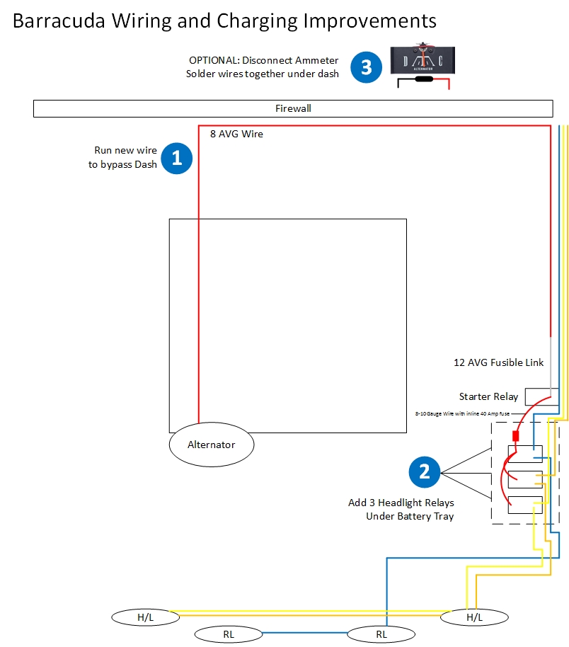
Here is an example of the bypass process. In your case, instead of adding headlight relays you would be adding relays or direct taps for the systems you need to use.
So this diagram proves my point. You are still tapping into the alternator stud...just through an 8gauge wire. When the car is running (and not discharging), the current source will be the alternator as it will provide a higher voltage (13.8-14.6V) than the battery itself (12.6-12.8V).
If you do the bypass from the alternator stud to the starter relay stud, this provides a much better path (less resistance) from the alternator to battery so it makes little difference now which "side" you tap from now. However, for an unmodified system, it does make a huge difference.
Those instructions are written universally for all cars...many of them having volt meters (no ammeters) and NOT pulling all the charging current through the firewall like these old Mopars.
For these old Mopars, not bypassed, best to pull from the alternator stud...period.
|
|
|
Re: Wiring directly to the battery, how do you do it?
[Re: Steve Bryant]
#1773994
03/08/15 12:32 PM
03/08/15 12:32 PM
|
Joined: Jul 2007
Posts: 1,526
North Carolina
cjskotni
pro stock
|
pro stock
Joined: Jul 2007
Posts: 1,526
North Carolina
|
Quote:
Yes, exactly. No argument with you cjskotni.
If you did not run a bypass and connected directly to the alternator then the load would still cross the bulkhead in the event the engine was not running and the device needed power.
That specific scenario is less common and would carry a lighter load but in the event you are running new lights or a large amp or large electric fans, I would personally run a bypass and create a new distribution point inside the engine bay so those loads could pull directly from the engine bay.
I agree the bypass isn't a bad idea if originality is not top priority. It will render the ammeter inaccurate but is safer and provides less of a voltage drop than the OEM harness. It should also be noted that if you do this, you should put a fusible link 2ga smaller than the bypass wire in-line, unless you are suicidal.
My main point was to refute the people on here who think that the voltage is somehow "clean" on the battery side of the harness and "shakey" on the alternator side. This is misinformation and simply not true. 
|
|
|
Re: Wiring directly to the battery, how do you do it?
[Re: markz528]
#1773997
03/08/15 03:29 PM
03/08/15 03:29 PM
|
Joined: Jul 2007
Posts: 1,526
North Carolina
cjskotni
pro stock
|
pro stock
Joined: Jul 2007
Posts: 1,526
North Carolina
|
Quote:
Quote:
Quote:
Not misinformation. All wires have some resistance and inductance. Just because they are the same "circuit" does not mean the same location. That same common circuit could be broken down showing small resistances due to wire length (and even connections) between each part of the circuit.
Having the connections closer to the battery, and on a different connection than the starter or other high current loads will also help prevent dips in the voltage when a high current load turns on. E=I*R
The inductance or capacitance of wire in a DC circuit is nill. When you get into the Ghz, that's a different story.
I agree that being on one side of the circuit vs another can result in higher or lower voltage which is due to resistance of the wire + connections in the bulkhead.
Also when a car is running, the alternator will be the source of the current, not the battery so your reasoning is backwards.
Have you measured the voltages/currents in a car? The "noise" is well into the megahertz range. And inductance and capacitance plays a huge role in the low megahertz range.
You can bet that the battery is the source to tie to when trying to minimize noise. The battery terminals are the closest point where you will have pure DC. The alternator is a rectified AC device and it will have a ton of noise on its output.
I still don't understand how you think something tied to the same circuit would experience more or less "noise". I have never seen any evidence or have any reason to believe an alternator would put out noise in the Mhz range. Assuming we rectify twice per cycle (pulley rotation), alternator turns 3x per engine RPM, gives (2 x 3 x 5000)/60 = 500 Hz (at 5000 engine RPM). Any "ripples" from this rectification are very small and would not affect anything but the most sensitive of electronics. If your alternator is putting out any appreciable noise in the Mhz range, you got a crap alternator. Even so the only thing that would be different from the alternator stud to the starter relay would be the amplitude of these fluctuations (and hence the DC output) which would be lower (hopefully by less than several 100mV) at the starter relay.
Again spreading misinformation and fear over nothing.
For the OP, if you are sick of this banter, just pull the 8ga bypass wire + 12ga fuse link from alternator stud to starter relay and then this doesn't matter. Your ammeter will be totally unreliable but you will get power where you need it and it will be safe.
I guess this will comfort the ignorant that, over that 8ga wire, all the high frequency Mhz "noise" from the alternator will suddenly melt away over 3 feet of 8ga wire since now you are tapping into all that "clean" battery juice now.
|
|
|
Re: Wiring directly to the battery, how do you do it?
[Re: Supercuda]
#1773999
03/08/15 07:10 PM
03/08/15 07:10 PM
|
Joined: Jan 2003
Posts: 4,293
Morrow, OH
markz528
master
|
master
Joined: Jan 2003
Posts: 4,293
Morrow, OH
|
The majority of the hf noise comes from the ignition system and much of it is induced (cross talk).
Because it is a high frequency it flows readily through capacitance (including stray capacitance)and is impeded by inductance (standard cables). Therefore the standard cables in our cars (don't care how big it is) are a high impedance to these high frequency currents.
Therefore the cable going to the battery is a LC filter and the battery is a big DC sink so the battery terminals are the cleanest battery signal you will find.
A shield in a shielded cable has a low impedance because of the coax effect - in a coax the inductance is nullified so it is a good conductor of high frequency.
At a couple of megahertz, would you believe that the electrons fly off the cable rather easily instead of flowing through it? Take a cable with 2 megahertz current going through it and give it a 90 degree bend - the impedance of the cable goes up a lot!.
It was very easy to prove when I was doing transfer impedance testing of high frequency cables. We learned you must keep the cables as straight as possible or they become transmitting antennas.
Believe it or not - but I have been nicely rewarded by my employer for chasing high frequency stray currents in industrial plants all over the world so I kinda understand them............
67 Coronet 500 9.610 @ 139.20 mph
67 Coronet 500 (street car) 14.82 @ 94 mph
69 GTX (clone) - build in progress......
|
|
|
Re: Wiring directly to the battery, how do you do it?
[Re: markz528]
#1774000
03/08/15 07:19 PM
03/08/15 07:19 PM
|
Joined: Sep 2007
Posts: 14,889
up yours
Supercuda
About to go away
|
About to go away
Joined: Sep 2007
Posts: 14,889
up yours
|
That's why an EMI filter shunts the unwanted frequency to ground. The filter cap on the alternator is hooked to the output stud on one end, ground on the other. As you said it passes it right thru. Same with the filter cap on the coil, shunted straight to ground.
Now that is not to say that the system designed back when these cars were new is the best for an EFI swap, it's not as it was designed to prevent unwanted noise in the audio of your radio, and that's 20khz or below. However, building one to suit isn't difficult either and probably a good idea regardless of where you pick off your source voltage.
Best was to see if you have EMI issues is with a scope, but darn few people have one and less know how to use them.
They say there are no such thing as a stupid question.
They say there is always the exception that proves the rule.
Don't be the exception.
|
|
|
Re: Wiring directly to the battery, how do you do it?
[Re: Supercuda]
#1774001
03/08/15 08:49 PM
03/08/15 08:49 PM
|
Joined: Aug 2003
Posts: 43,355
Bend,OR USA
Cab_Burge
I Win
|
I Win
Joined: Aug 2003
Posts: 43,355
Bend,OR USA
|
Have you ever taken a capacitor apart? If not you should  It might help you understand how they are constructed, there is a insulator in between both electron storage devices, not a direct path to ground from one side to the other  If there was a direct path to ground that would be a short, shunt, correct  A capacitor will store electrons(voltage, milli amps and so on) when charged and discharge them to ground at the first opportunity(IE neon lights and capacitor start electric motors as well as other applications)  I learned that lesson in high school auto shop the hard way by the instructor telling us not to touch them (one on each desk not charged) until intsructed to on what they are and what they do and that they can hurt you, get your attention  , if not handled correctly. One of the upper classmen had charged several of them, mine included when the intsructor had went out of the classroom during class break EMF, electromotive interference can be induced into semi conductor circuits in many different ways, RMI, Radio Magnetic interference can be also. Both can and will adversely affect many low voltage circuits controlled by computers The car battery, like all batterys, is a energy(voltage and amperage) storage device, the alternator takes direct current to operate it, it cannot generate electricity like a generator can, and amplifys it to a higher A.C. voltage and then converts it back down to direct current to charge the battery and provide all the current to run the circuit load the car has. If the alternator is to small to carry the operating load the battery will go dead eventually Hence the increase amperage output of todays alternators, the bigger the load the more current, energy, needed to operate it One more time on direct current flow in cars, the current is taken, output, flows from the negative side of battery, NOT THE POSITIVE SIDE The only time D.C. elctrons flow from postive to negative is inside the battery, not outside  The alternator charges into the positive side of the battery after all the other circuits are fed, our old Mopars route all the charging current from the alternator through the amp gauge and then back to the battery, not the opposite GM and Ford used parelel inductive circuits on there amp gauges, when provided OP, follow the instructions from the manufacturer on your EFI installation  They've already went through all the grief on reserach and development on thier new products and know what the customer needs to do during the installation to avoid problems on thier products Some people, mechanics and technician of all sorts, don't or won't read the installtion instructions until they run into problems, many times self induced I hope this helps some of you
Mr.Cab Racing and winning with Mopars since 1964. (Old F--t, Huh)
|
|
|
Re: Wiring directly to the battery, how do you do it?
[Re: cjskotni]
#1774002
03/09/15 12:32 AM
03/09/15 12:32 AM
|
Joined: May 2011
Posts: 220
Aurora, CO
jbeintherockies
enthusiast
|
enthusiast
Joined: May 2011
Posts: 220
Aurora, CO
|
Quote:
Also when a car is running, the alternator will be the source of the current, not the battery so your reasoning is backwards.
That is not true. If the electrical system of the car requires 50 amps and the alternator can only provide 40 amps, for example, the system will begin to draw from the battery.
|
|
|
Re: Wiring directly to the battery, how do you do it?
[Re: jbeintherockies]
#1774004
03/09/15 12:44 AM
03/09/15 12:44 AM
|
Joined: Jan 2003
Posts: 18,428
UPPER MICHIGAN, MARQUETTE COUN...
NITROUSN
I Live Here
|
I Live Here
Joined: Jan 2003
Posts: 18,428
UPPER MICHIGAN, MARQUETTE COUN...
|
Quote:
Quote:
Also when a car is running, the alternator will be the source of the current, not the battery so your reasoning is backwards.
That is not true. If the electrical system of the car requires 50 amps and the alternator can only provide 40 amps, for example, the system will begin to draw from the battery.
A very important point.
|
|
|
Re: Wiring directly to the battery, how do you do it?
[Re: StrkrDart69]
#1774006
03/09/15 03:48 AM
03/09/15 03:48 AM
|
Joined: May 2008
Posts: 5,399
Aurora, Colorado
451Mopar
master
|
master
Joined: May 2008
Posts: 5,399
Aurora, Colorado
|
The original poster was asking about connecting EFI and MSD. The FAST EFI instructions are very specific about connecting to the battery.
I think it would be OK connected to some other battery voltage source if the wire size is adequate with good connections and no large current changes on the line.
Much of what has been discussed is a matter of degree. Connecting loads like lights and fans off the alternator works fine because it is not a problem if there is noise on the power line to those devices. The possible down side is there could be a slight change in the regulated voltage depending on where the voltage regulator sense line is connected (internal regulated, regulated sensing battery voltage, or somewhere in between?), again the effects would likely be too small to make a difference in our application unless there is fairly large resistances, like 0.10 Ohm, in the wires and connections. For example, alternator charging battery at 10-Amps, that 0.10 Ohm is a 1.0 Volt drop between the alternator and Battery.
The circuits in the EFI are much more sensitive to noise. The voltage inputs are fed to analog-to-digital converters that are converting voltages at a high frequency and feeding the information to the processor which calculates ignition timing and injector pulse timing, and then controls the power to the injectors, ignition coil and other output devices. I'm sure the manufacturers design in quite a bit of filtering, but I'm sure many problems called into support were because of connecting the EFI unit to power incorrectly.
|
|
|
Re: Wiring directly to the battery, how do you do it?
[Re: Cab_Burge]
#1774008
03/09/15 08:44 AM
03/09/15 08:44 AM
|
Joined: Jan 2005
Posts: 3,699
Newport, Mi
Evil Spirit
master
|
master
Joined: Jan 2005
Posts: 3,699
Newport, Mi
|
Quote:
Does anyone who has put comments on this post understand current flow in D.C.(Direct Current) circuits? If I understand(edited) the operation of the electrcial operated injectors on EFI systems they pulse the negative(battery) side of the injector with -5.5 volts, correct , ? If so then doesn't all the elecrtons need to return to thier source to complete the circuit?(make the injectors pulse) That being said you might want to follow the instructions from the manufacture to the T
Probably not correct . Factory EFI systems usually feed 12V+, NOT 5.5 VOLTS to the injectors, along with 12V+ to the coil from the same circuit. Then, yes, they do pulse the ground circuits to cycle the injectors and coil. The 5.5 volt circuit is usually the sensor voltage circuit - MAP sensor, CPS, TPS, O2's, etc. Since most of the factory EFI's can use the same injectors as the aftermarket MPFI's do, safe bet the aftermarket uses 12V for their systems, too.
As to the alternator/noise issue - I can tell you that the "purity" of the DC current can vary greatly from alt to alt. Installing high dollar stereo systems years ago taught me a simple test - when you can unplug the alt field wires from the alt when the engine was running and the whine in the speakers would usually go away - well, common sense tells you it isn't the ignition making the noise.
Oops, almost forgot  
Free advice and worth every penny...
Factory trained Slinky rewinder.........
|
|
|
|
|


