|
 Re: Wire guage
[Re: NachoRT74]
#618682
Re: Wire guage
[Re: NachoRT74]
#618682
03/03/10 01:14 PM
03/03/10 01:14 PM
|
Joined: Aug 2007
Posts: 6,108
Valencia, España
NachoRT74

master
|
master
Joined: Aug 2007
Posts: 6,108
Valencia, España
|
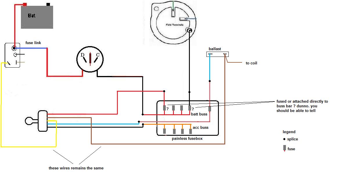
then as far I can tell by the instructions, this will be the new setup at least for main starting and charging circuits
NOTE... I DON'T KNOW IF ALT WIRE AND IGN SWITCH WIRE ARE FUSED OR NOT, being simple spliced in to batt buss bar. I simply ilustrated like they are fused, but if they are the shgould be BIG CAPACITY FUSES... 40, 50 or 60 amps fuses.
remember this is just what I supose it is without have in hands the fusebox
I'm based on how it works any Mopar Body ( except those with starter solenoid with coil ballast bypass provision, on lates 70 )
With a Charger born in Chrysler assembly plant in Valencia, Venezuela
|
|
|
Re: Wire guage
[Re: 70duster340]
#618685
03/03/10 03:23 PM
03/03/10 03:23 PM
|
Joined: Aug 2007
Posts: 6,108
Valencia, España
NachoRT74
master
|
master
Joined: Aug 2007
Posts: 6,108
Valencia, España
|
next step... lighting circuit
As I can see, the painless fusebox only provides one fuse and circuit for all the lighting system, for a while Mopar uses 2 inputs and 3 outputs being the two inputs:
-Black wire ( traced white ? ), unfused, coming from alt wire ( as several diagrams did show ). Even is "unfused", remember the system is protected by the fuse link
-Pink wire, fused coming from batt/alt source too
the three outputs:
-green wire... headlights. Is ONLY FEEDED BY THE BLACK ( traced white ? ) WIRE
-Black wire ( normally traced yellow )... parking lights and sidemarkers. Is feeded ONLY by the pink fused input
-Orange wire... Dimmered source to cluster and stuff. Is feeded by the same PINK wire, and does have an EXTRA fuse on the line before get the bulbs
Now, to make it work in a Mopar way, this is my suggestion:
Splice the black ( traced white ? ) wire into the same MAIN SYSTEM POWER wire. You can also splice it in to the ammeter stud, black side.
Splice the pink wire ( was arriving to your original fusebox ) into the red traced white new fusebox wire
The tan wire to the dimmer function what becomes into the orange wires after the original fusebox can it be spliced together. System is already protected by the fuse existing to the red traced wire ( originally pink ), but you can also fit a separated fuse cap and splice in between the tan and orange wires. Tan and Orange wires were both arriving to the original fusebox to a separate fuse from both buss bars ( acc and batt )
With a Charger born in Chrysler assembly plant in Valencia, Venezuela
|
|
|
Re: Wire guage
[Re: 70duster340]
#618689
03/03/10 04:13 PM
03/03/10 04:13 PM
|
Joined: Aug 2007
Posts: 6,108
Valencia, España
NachoRT74
master
|
master
Joined: Aug 2007
Posts: 6,108
Valencia, España
|
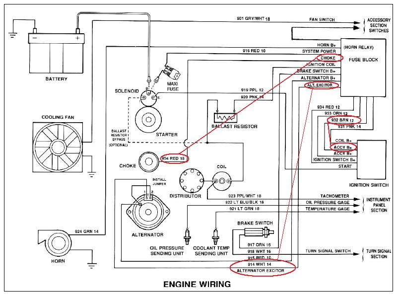
please can you check what input source feeds the white wire to the "regulator" as instruction sheet states on point 8
ATTACH THE WIRE GOING TO THE IGNITION SWITCHED TERMINAL OF THE ALTERNATOR REGULATOR (INTERNAL OR EXTERNAL) TO THE ALT IGN B+ TERMINAL. (WHITE WIRE) THIS WIRE TURNS ON THE REGULATOR WHEN THE IGNITION SWITCH IS TURNED ON. (14GA)
ACC buss bar ? Coil wire ? some Ign swicth wire ?
Then also on Diagram is shown a red wire 18 gauge to feed the choke... same question... what source feeds that wire ? ACC buss bar ? some IGN switch wire ?
Remember the Painless diagram shows an extra ACCY WIRE brown 12 gauge
With a Charger born in Chrysler assembly plant in Valencia, Venezuela
|
|
|
Re: Wire guage
[Re: 70duster340]
#618691
03/03/10 05:37 PM
03/03/10 05:37 PM
|
Joined: Aug 2007
Posts: 6,108
Valencia, España
NachoRT74
master
|
master
Joined: Aug 2007
Posts: 6,108
Valencia, España
|
Ok this is what I see. -first the initial idea what I like more, for the starting-charging circuit:  -then both circuits fused using the ALTERNATOR wire ( white wire ):  what I don't like from the second diagram double fused option: -Engine will remain feeded when you set the ign switch power to ACC. why would you need to keep engine parts ( such as alt, reg, field, choke, ECU if existant ) powered IF YOU JUST WANT TO LISTEN THE RADIO ( for example ) -Everything will be feeded by just one point inside the ign switch, and one wire, black coming from ign switch. Then you can splice both blue and black wires to share the load, but honestly doesn't need for that -Why would you need to fuse the coil power at starting moment if it just work AT STARTING MOMENT ? rest of the time will just work the regular RUN circuit -In fact the original painless diagram shows this wire/fuse to run directly to ballast, so then to coil, making the ballast bypass from starter relay ( optional ). This setup was built on lates 70s Mopars. For a while bypass from the starter relay didn't exist, the ign switch was who made it. There are more options to use this white wire toward to engine parts, but will need to get inside the engine harness, modify it, use an extra cavity of bulkhead. Once again no need for that
With a Charger born in Chrysler assembly plant in Valencia, Venezuela
|
|
|
Re: Wire guage
[Re: NachoRT74]
#618692
03/03/10 06:07 PM
03/03/10 06:07 PM
|
Joined: Aug 2007
Posts: 6,108
Valencia, España
NachoRT74
master
|
master
Joined: Aug 2007
Posts: 6,108
Valencia, España
|
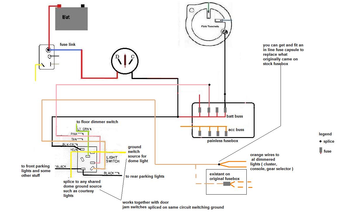
My lights circuit suggestion remains the same ( more detailed diagram ) As stated before you can run and splice the black traced wire to feed headlights into the SYSTEM POWER WIRE or fit an eyelet terminal on it and attach it to the Ammeter stud. You choose. The original pink wire to lights switch is already around original fusebox of course. However check wich one, because there are couple more of pink wires around.  Also, you can splice the orange cluster ( dimmed source ) wires with the tan wire coming from dimmer lights switch. Both wires are really close to splice them together since the original fusebox already had those wires linked with an extra fuse, separated from both existant buss bars. You can also install a fuse holder in between too keep the original setup, just that the fuse will be floating on harness a fuse holder like this:  once again is your choice EXTRA NOTE ( not at diagram ): the cigar lighter is originally spliced at the same point/fuse where the pink wire takes the power and feeds input to parking lights. Is not ilustrated, but the red wire for the cigar lighter can still keep spliced to the same wire/fuse than the pink wire to parking lights input ( so the same red traced black wire at new fusebox )
Last edited by NachoRT74; 03/03/10 09:06 PM.
With a Charger born in Chrysler assembly plant in Valencia, Venezuela
|
|
|
Re: Wire guage
[Re: NachoRT74]
#618693
03/03/10 07:10 PM
03/03/10 07:10 PM
|
Joined: Aug 2007
Posts: 6,108
Valencia, España
NachoRT74
master
|
master
Joined: Aug 2007
Posts: 6,108
Valencia, España
|
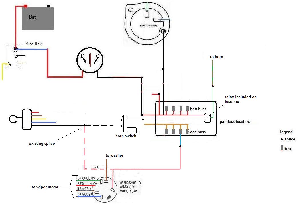
Next... horn and wiper... pretty much straight up with some notes.
Locate the horn relay and will find the black and green/red wires. Black is ground to activate the relay. Green/red is the definitive positive output source to sound the horn. These are the two wires what will splice into the new fusebox ( points 2 and 19 at instruction sheet ). I guess the relay takes the power from the Batt buss and has a fuse too but I didn't draw the fuse to relay on diagram.
ONE NOTE ABOUT THE HORN RELAY...
The original relay is also a keys in buzzer warning signal. This relay drives two black wires, both coming from steering column. The black horn wire is grouped together with the horn functions and comes from turning switch harness plug. The buzzer black wire is a separated prong on relay and comes from ign switch harness plug ( becomes red into the column )
Next question. Do you want to keep working the ign key in buzzer function ? if so, then you will need to keep the original horn relay on harness to make it work still being feeded by the violet wire. Diagram shows this wire being feeded FROM THE ORIGINAL MAIN SPLICE AT ALT WIRE. Is this violet wire still being energized from there or somewhere ?
Then to note is you'll have two horn relays now, one just for the horn ( new ) and the original one just for the buzzer ( old ) are you agree keeping both relays ?
You can also forgett about the new relay at Fusebox and keep the original one. Once again your choice
----------------
Wiper pink wire shows on original diagram SPLICED SOMEWHERE INTO THE ACC WIRE COMING FROM IGN SWITCH. Locate this wire and now will splice into a fuse now at the new fusebox as isntruction sheet says, blue wire ( point 3 )
With a Charger born in Chrysler assembly plant in Valencia, Venezuela
|
|
|
Re: Wire guage
[Re: NachoRT74]
#618694
03/03/10 07:53 PM
03/03/10 07:53 PM
|
Joined: Aug 2007
Posts: 6,108
Valencia, España
NachoRT74
master
|
master
Joined: Aug 2007
Posts: 6,108
Valencia, España
|
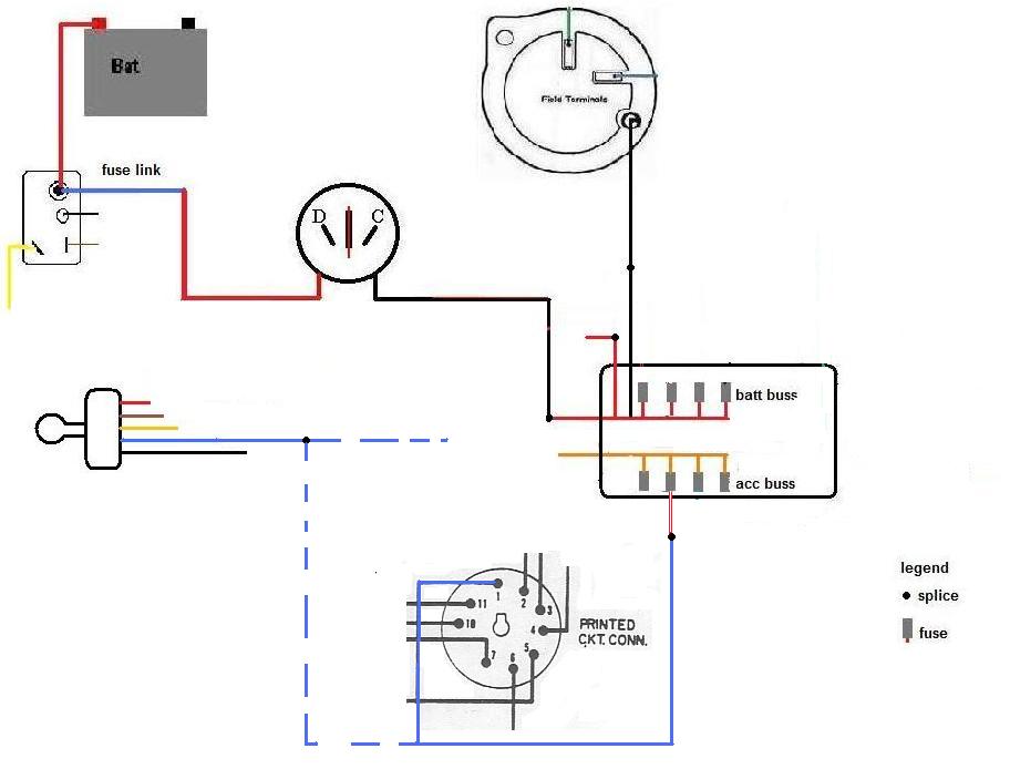
instrument cluster feed.
As the 71 valiant diagram shows from mymopar website, the cluster feed wasn't fuse protected either ( I stated earlier some models weren't fused there ) and were spliced directly from the RUN circuit at ign switch.
making this change the cluster gauges ( voltage limiter ) and warning lights will be fused protected.
NOTE: Making this change you won't have any gauge reading or idiot light ( oil, brake ) working for a while you are cranking. The original setup did keep work the dash instruments working when cranking since the ballast resistor was feeding back the cluster/blue wire from the Coil ( ballast bypass ) wire. Dimmered power since it was throught the ballast resistor but still working. Take that in mind.
wire is dark blue traced. There is another dark blue wire at a side arriving to cluster but is the gas sender one.
With a Charger born in Chrysler assembly plant in Valencia, Venezuela
|
|
|
Re: Wire guage
[Re: NachoRT74]
#618695
03/03/10 08:50 PM
03/03/10 08:50 PM
|
Joined: Aug 2007
Posts: 6,108
Valencia, España
NachoRT74
master
|
master
Joined: Aug 2007
Posts: 6,108
Valencia, España
|
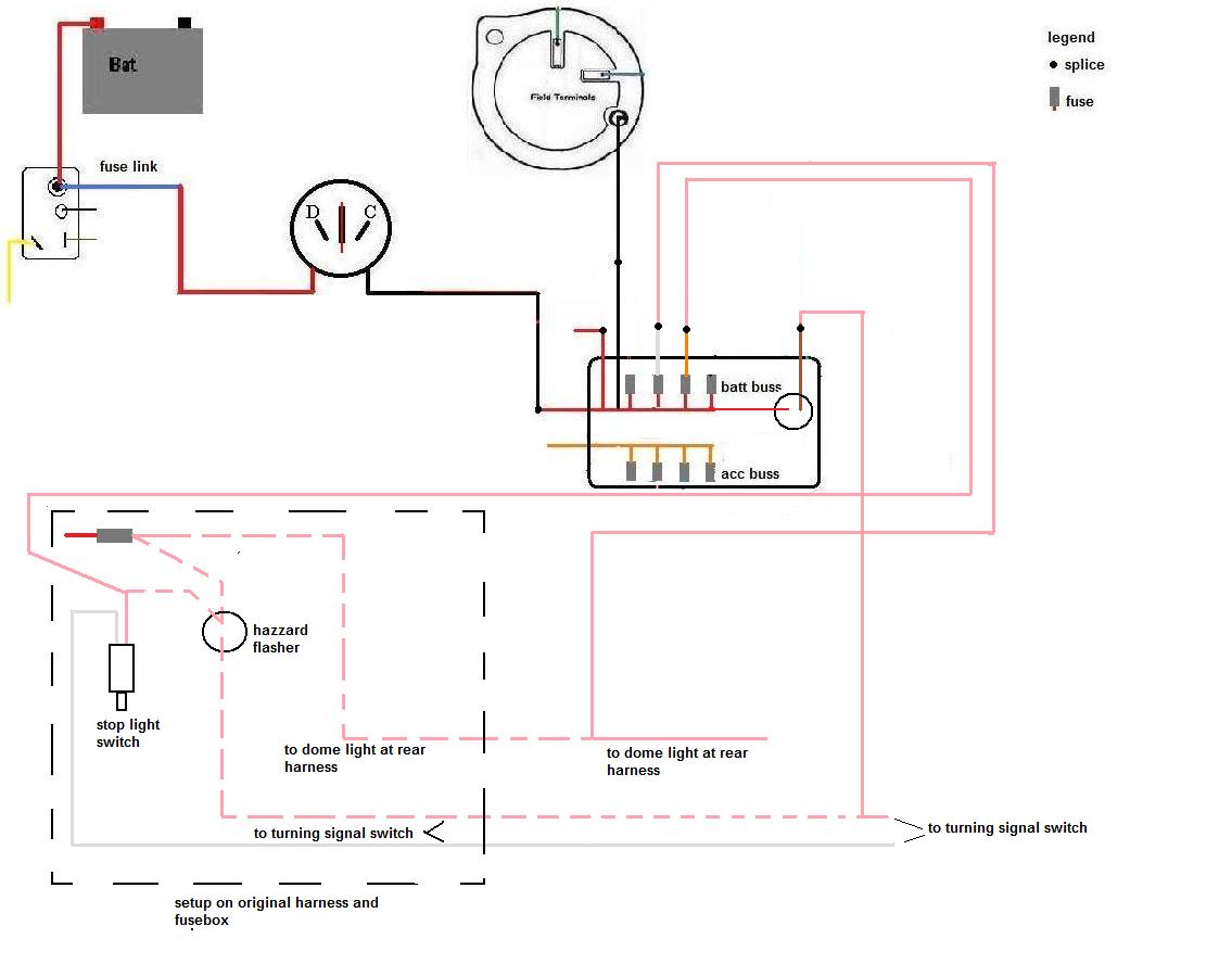
now, some stuff will need to work on at the same time. On Mostly of Mopars, and more specifically on your Valiant, all the dome, stop and hazzard circuits are protected by just ONE fuse. Why is that ? because is not normal you'll have everything working at the same time. In fact since 1970 is totally imposible to make work the brakes and the hazzards at the same time by the turning switch configuration.
The new painless fusebox provides you the chance to fuse them independently (sp?), but will need to pay attention on what are you doing.
first the discontinued line box shows how's wired the original setup, everything linked to one fuse coming from the batt buss.
The discontinued lines will show what lines WILL BE GONE by the end of the job, including the flasher, since the painless box gives you a flasher on circuit
will need to make a good track on these wires to make the correct splices.
as usual on all my diagrams, color are correctly matched with both setups.
Once again, I assume the hazzard flasher is fuse protected from batt buss bar, just that I didn't draw the fuse for it on diagram
With a Charger born in Chrysler assembly plant in Valencia, Venezuela
|
|
|
Re: Wire guage
[Re: 70duster340]
#618698
03/04/10 01:02 AM
03/04/10 01:02 AM
|
Joined: Aug 2007
Posts: 6,108
Valencia, España
NachoRT74
master
|
master
Joined: Aug 2007
Posts: 6,108
Valencia, España
|
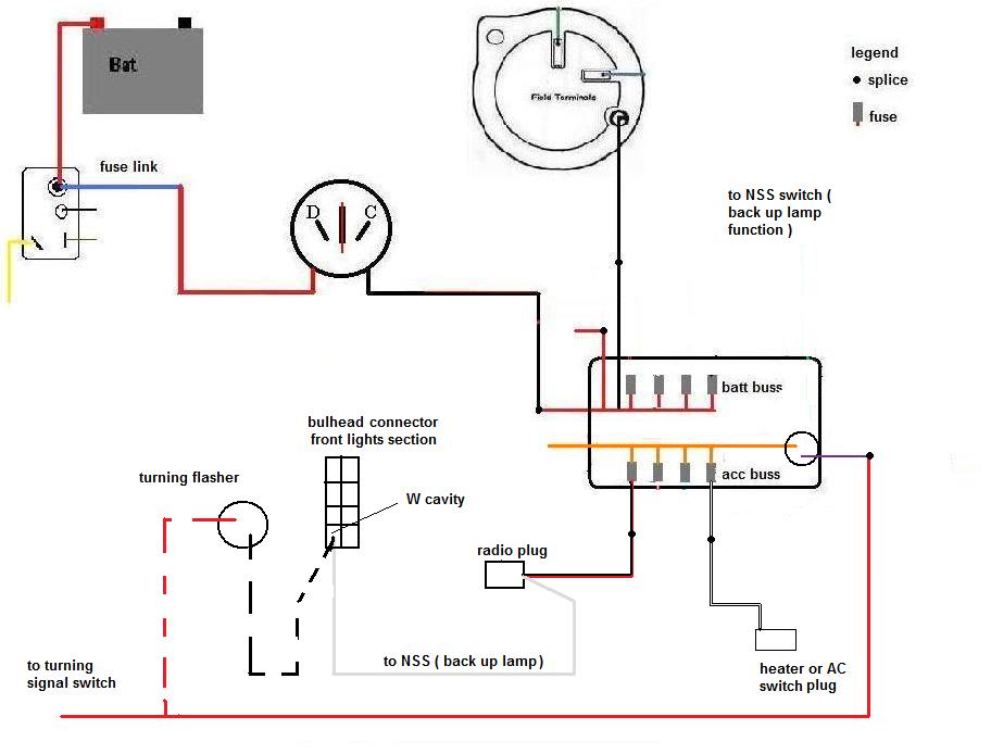
LAST SECTION, what still rst of the acc section:
-turning signal
-Radio
-Heater/AC
Heater is pretty much straight up and even color matches. That wiring was already arriving to fuse box. Is a cut and splice on new fusebox job
Radio. Allmost the same. Instruction sheet doesn't say the wire color for this RADIO B+ so I draw same original color being spliced. Same as above you'll find is a cut from original fuse and splice on the new one. Will need to consider this circuit also feeds the BACK UP LAMP at bulkhead, being spliced from Radio Plug itself, and will remain in that way
Turning flasher doesn't have its own fuse, Shares same fuse than Radio/Back up lamp, so is spliced on same circuit, but from bulkhead ( W cavity ). This splice can it be removed together with flasher itself, and now the red wire going to turning switch from the turning flasher will be spliced into the purple wire at new fusebox. As stated on instruction wheet this wire already have the flasher on circuit ( I guess also fused ).
I think this covers all the circuits. If some more doubt, will be happy to clear up!
With a Charger born in Chrysler assembly plant in Valencia, Venezuela
|
|
|
Re: Wire guage
[Re: NachoRT74]
#618699
03/04/10 01:11 AM
03/04/10 01:11 AM
|
Joined: Aug 2007
Posts: 6,108
Valencia, España
NachoRT74
master
|
master
Joined: Aug 2007
Posts: 6,108
Valencia, España
|
you should get not using from painless fusebox the ELECT FAN wire and the ALTERNATOR/REGULATOR wire since those functions are unexistant on the stock setup. You can use them on any extra function you wish to give power from ACC section.
REMEMBER I DIDN'T DRAW THE STOCK CIGAR LIGHTER source. It can be spliced at ant batt fuse you want, If you want to keep the stock setup, it should be spliced together with the pink wire of the lights switch ( arriving to red traced black at new fusebox )
Parallel wires from alt and batt simply will arrive directly to ammeter studs, Nothing to do with the new fusebox
With a Charger born in Chrysler assembly plant in Valencia, Venezuela
|
|
|
Re: Wire guage
[Re: 70duster340]
#618701
03/04/10 04:08 PM
03/04/10 04:08 PM
|
Joined: Aug 2007
Posts: 6,108
Valencia, España
NachoRT74
master
|
master
Joined: Aug 2007
Posts: 6,108
Valencia, España
|
Do you mean keeping the ballast wires and circuits ( blue and brown, RUN and START ) like stock without fuse ?
Yes you can do it, is not a bad idea... never though on that because I was making the setup with the Painless fusebox option to "coil"
how many amps ? 5 max. Original fuse for dimmer source is 5 as far I remember on my Charger. It should be casted on your original fusebox and stated on car's owners manual. Maybe A bodies are smaller due they use to use less bulbs to dash.
Remember if you still wire the dash instrument like the point #11, gauges ( and warning lights ) will still turned off when cranking. It is originally wired in to the RUN ( blue ) circuit, and now is being souced by ACC by painless, what doens't get the feedback power spliced from cranking circuit at ballast
With a Charger born in Chrysler assembly plant in Valencia, Venezuela
|
|
|
|
|


