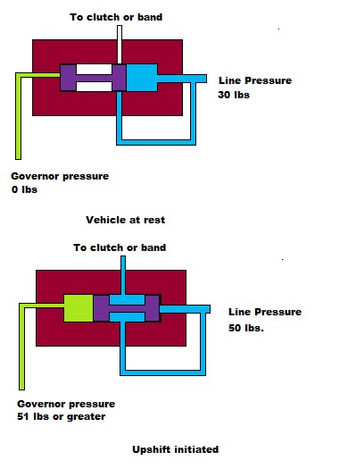
Here's a simplification of a shift valve in a transmission and how the governor and line/throttle pressure work to initiate an upshift or downshift.
The throttle linkage moves the throttle valve which in turn varies the line pressure up or down. More throttle equals more pressure. This higher pressure does two things. It delays the upshift as well as the pressure applied to the psiton or servo that applies the clutch or band. The governor pressure varies according to output shaft speed. The faster the output shaft turns, the higher the governor pressure. Actually it is a two stage process in a Torqueflite, but for this discussion the pressure rises as output shaft speed goes up.
Now if you look at the first diagram you can see that the line pressure is greater than governor pressure so the valve stays shifted to the left and shuts off the supply to the clutch or band. As road speed goes up the governor pressure starts to rise and when it reaches a point where it is higher than the line pressure holding the valve, the valve moves to the right and opens the passage to the clutch or band. If the throttle is pressed harder, line pressure goes up so the governor pressure needs to be higher (faster output shaft speed) in order to overcome the line pressure to initiate an upshift.
This is a real simplification of the process as there are different size lands on the shift valves to vary the required pressures, boost valves, accumulators, special sized orfices to slow an apply or release speed, but this simple diagram illustrates the need for the throttle linkage. Without it, the shift speeds and pressures are not correct and will burn up the clutches and bands.


