|
|
 Re: Roadrunner Dust Trail Placement
[Re: macmic87]
#1416349
Re: Roadrunner Dust Trail Placement
[Re: macmic87]
#1416349
04/07/13 11:26 PM
04/07/13 11:26 PM
|
Joined: Jan 2003
Posts: 17,524
Las Vegas, NV
6bblgt

I Live Here
|
I Live Here
Joined: Jan 2003
Posts: 17,524
Las Vegas, NV
|
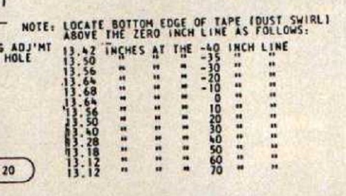
According to the factory drawing in the other thread  the "dust trail" V6Y stripe is NOT a straight line ..... it's an arc, it comes out of the "scoop" level then moves up hill (~1/2") toward the wheel opening - then back down (~3/8") to the bird on the front fender. WOW!!  (I'll "assume" the stripe makes the "arc" to avoid the fender wheel opening that the center stripe on a GTX just barely clears.)
Last edited by 6bblgt; 04/08/13 03:38 PM.
|
|
|
Re: Roadrunner Dust Trail Placement
[Re: 6bblgt]
#1416355
04/11/13 02:37 PM
04/11/13 02:37 PM
|
Joined: Jan 2010
Posts: 600
Vicksburg, MI
coffeeman383
mopar
|
mopar
Joined: Jan 2010
Posts: 600
Vicksburg, MI
|
Quote:
I guess the question is "where is the 0 inch line" that all the dimensions are referenced to?
I went home and tried to determine where the �zero inch line� (on that drawing from the other thread) would be for the vertical and horizontal measurements based on my 70RR with just a fender bird (not sure if original). Here�s what I got (and I don�t like it)�
Vertical zero is NOT the pinch weld, style line, door edge, wheel centers, or obvious frame points. As near as I can tell, it�s at the left side Chrysler symbol. I based this on laying down a masking tape �dust stripe� and measuring stuff and looking for landmarks approx 13.27� down. There is nothing else obvious on the side of the car. On a frame drawing from the service manual, �0� is measured as wheel center line. Not the same zero.
Horizontally I come up with zero being the front edge of the cowl! This is pretty close to having the fake scoop edge at +75� and puts the beak of the bird at -45� (per that factory blueprint). I wish it was again the pentagon but it�s not.
The bird on my car is NOT beaked at -45� but again I don�t think it is original or didn�t matter as there was no dust stripe.
The frame drawing shows some gauge holes on frame cross members but nothing really aligns with the +75� scoop placement.
I don�t like my answer. Having two different elements for zero lines makes no sense.
|
|
|
|
|
|
|


