|
 Re: Gen III Hemi, please post things to avoid and know..
[Re: gregsdart]
#1370132
Re: Gen III Hemi, please post things to avoid and know..
[Re: gregsdart]
#1370132
03/02/15 09:21 PM
03/02/15 09:21 PM
|
Joined: Jan 2004
Posts: 8,248
fredericksburg,va
cudaman1969

master
|
master
Joined: Jan 2004
Posts: 8,248
fredericksburg,va
|
Quote:
Throttle body selection info pirated from another forum!
An LX member sent me a message asking, “What size TB do I need?”, and I realized that there really wasn’t a clear answer to his question. Oversize TBs are readily available, but they don’t come with any sort of recommendations or technical info to help with the decision. The vendors that offer these things aren’t even providing actual flow numbers for their products. The lack of info has cause TB selection to be quite the debatable topic. Therefore, I’m going to attempt to make some sense of the matter with the aid of an ordinary scientific calculator, a few common formulas, and even a little geometry.
First, I’ll explain in detail how flow area of each TB will be established. We’ll essentially determine effective flow area for each TB we want to use in our calculations. We are going to look at 80mm, 85mm, and 90mm. First we figure the total area of the round “hole”. We, then subtract the area of the 10mm throttle shaft. To improve accuracy, we’ll multiply this area by a value for discharge coefficient (cd). A reliable source tells me a 90mm TB flows 1006cfm at 20”/H2O. We’ll use this info to get our “cd”, and assume that all TB sizes exhibit this value. The math………
(90mm / 25.4)^2 x pi / 4 = 9.86in^2 bore area
(90mm / 25.4) x (10mm / 25.4) = 1.395in^2 throttle blade area
9.86in^2 – 1.40in^2 = 8.46in^2 total area
calculating theoretical max cfm from area…..
(20in/H2O)^.5 x 66.2 = 296.1fps
9.86in^2 x 299.1fps / 2.4 = 1054cfm (theoretical max)
1006cfm / 1054cfm = .955 cd
8.46in^2 x .955cd = 8.08in^2 effective flow area
….Calculating for the other two sizes gives us the following values for our three TB sizes….
80mm = 6.26in^2
85mm = 7.14in^2
90mm = 8.08in^2
In order to calculate the TB size we need, we must figure how much air we are using. ? For this, we can use the infamous “carb sizing” formula.
Eq.1 cfm = (CID x RPM x VE%) / 3456
If we look at the term “cfm”, or ft^3/m, we see that it is the product of an area(ft^2) and a velocity(ft/m), resulting in a simple flow analysis equation that can help determine the size we nee, based off of flow area.
Flow (cfm) = Area(ft^2) x Velocity(ft/m)
...adding a constant to convert units…..
Eq.2 cfm = in^2 x fps / 2.4
So we now have a simple way to solve for TB size, based on area, given that we have values for velocity and cfm. We’ve already tackled cfm. So, how do we our velocity values? 4bbl carbs are typically flowed at 1.5 inches of Hg. However, unrestricted carbureted engines typically see 0.8-1.2 inches of Hg at peak power. We’ll use these values, multiplying by 13.61 to convert from Hg to H2O. To get our velocity, we’ll use a formula common to any head porters who uses a pitot probe. Here are the formulas in action…..
Eq.3 (in/Hg x 13.61)^.5 x 66.2 = Velocity (fps)
(0.8 x 13.61)^.5 x 66.2 = 218.4fps
(1.2 x 13.61)^.5 x 66.2 = 267.5fps
Let’s take a look at what the factory did. We’ll use 5400rpm for the 5.7L engine and 6200rpm for the 6.1L mill. Let’s also use 100% VE for stock performance of 345hp and 440hp, respectively. Using Eq.1…..
(345 x 5400 x 100%) / 3456 = 539cfm
(370 x 6200 x 100%) / 3456 = 664cfm
Now we calculate for area. We’re going to use 218.4fps for the 5.7L and 267.5fps for the 6.1L. I’m wondering if the same TB that was designed from scratch for the 5.7L engine was used on the 6.1L simply to satisfy the accounting department. Let’s use Eq.2 and see…….
539cfm x 2.4 / 218.4fps = 5.923in^2
664cfm x 2.4 / 267.5fps = 5.957in^2
…We can also work the math backwards, plugging in 6.26in^2 for the stock TB….
539cfm x 2.4 / 6.26in^2 = 206.6fps
664cfm x 2.4 / 6.26in^2 = 254.6fps
It appears that the decision to use the same TB on both engines was, indeed, made by the accountants. It also appears that they left a bit of room for a few bolt-on performance mods. Most importantly, the factory engineers agree with our .8-1.2 “/Hg range. Feeling confident with the math, let’s run the numbers for our fellow LX member and make a recommendation. He has a 423 stroker with ported heads and a custom grind cam suited for a 3600 stall TC, 5600 hp peak and a 6400 shift point with excellent VE%. Calculating for 0.8 and 1.2, or 218.4fps and 267.5fps, respectively….
(423 x 5600 x 116%)/3456 = 795cfm
754cfm x 2.4 / 218.4 = 8.73in^s
754cfm x 2.4 / 267.5 = 7.13in^2
That particular engine would need a full 85mm at minimum and could make use of a TB even larger than the 90mm piece. I wouldn’t even recommend one of the ported stock jobs for this particular application. The stock throttle blade diameter is still the restriction. Of course, with the 85mm and the 90mm being the same price, he might as well go for the 90mm and be done with it.
At this point, someone is thinking, ”yeah, yeah, but how power is it worth? And for how much?” Well, the dyno numbers and e.t. slips speak for themselves. However, power is determined by the air MASS we move through the engine and effectively burn. So, I done a little research and found a formula that calculates air density, based on barometric pressure and temperature. If temperature and VE% stay the same, we should be able to calculate, with fair accuracy, the change in air mass, thus power output. If VE% changes, then the difference will be even greater, meaning that our calculation is on the conservative side. We’ll use 29.921 “/Hg for standard barometric pressure. Doing all the math for the stock 80mm TB and the 90mm piece, we get 1.56”/Hg and .945”/Hg, respectively. 80�F seems like a reasonable number for intake temp. The calculation….
Eq.4 1.325 x (inches of Hg / (temp�F + 460)) = air density
1.325 x (29.921-1.56) / (80+460) = .0696lbs/ft^3
1.325 x (29.921-.945) / (80+460) = .0711lbs/ft^3
.0711 / .0696 = 1.02
So, we would have a difference in mass of 2%, and that same difference in output. But, remember, this is assuming that VE% remains constant. In reality, the smaller TB would, indeed, cause a restriction in flow and have an adverse effect on VE%, making the difference even greater. Also, we would incur additional pumping losses from running under greater vacuum.
Alas, we shall remain conservative and take a look at this 2% from a cost perspective. It just so happens that the guy with the 6.1L Super Stock football upgraded his mill with heads and a cam, only to capture the 6.1L modified football. $3200 worth of parts netted him 59hp, or an increase of 13%. Add another $1000 for installation, and we get $323 per 1% increase. Cast TBs can be had for $500, resulting in the upgrade cost of $250 per1% increase. This means that a 90mm TB would have a higher bang for buck value than even a head/cam swap on a 423 stroker. If VE% differs between the stock and 90mm, even the shiny billet TBs begin to have a favorable bang for buck value on this size engine.
It is kind of unfair to do all the work for one guy, and leave everyone else out. Therefore, I made a nifty excel sheet to calculate for the most common Gen III Hemi displacements. I used VE% of 110 for the chart, suggesting a fairly stout, efficient package. Here, for the first time ever, is a chart to help with TB selection, based on rpm.
Using the chart is simple. If peak power is higher than the rpm in the 1.2 “/Hg column, or peak torque is higher than the rpm in the 0.8”/Hg column, then you should really consider an upgrade. If peak power is higher than the rpm in the 0.8”/Hg column, or your shift point is is higher than the rpm in the 1.2”.Hg, an upgrade can be of benefit in an “max-effort” application, but isn’t absolutely necessary. I even included accompanying power outputs, so you can also make a selection based off of expected N/A power.
Throttle Body Selection Chart
-----------80mm ----------85mm ---------90mm
---------0.8-1.2"/Hg ----0.8-1.2"/Hg ----0.8-1.2"/Hg
345_____5190-6360_____5920-7250_____6700-8200
370_____4840-5930_____5520-6760_____6250-7650
392_____4570-5590_____5210-6380_____5900-7220
426_____4200-5150_____4790-5870_____5420-6640
440_____4070-4980_____4640-5680_____5250-6430
N/A hp____360-500_______440-580_______510-660
Now, let’s take a look for the forced induction guys. A lot of people seem to think that the blower cars could benefit from a larger TB even more than the N/A guys. Let’s take a look. I will be using some additional formulas, mainly intended to help with compressor selection. The main differences are in air density and temperature, although I’ll be looking at flow before the compressor, too, for those who are entertaining the idea of relocating the TB to this place. The standard “carb sizing” formula is used here as well, suggesting that the engine determines the actual volume of air that is moved. The compressor only changes density, by way of temperature and boost. We must find a way to determine the temp of the air going in the engine. To do this we first figure temp of the air exiting the compressor. Then, we use our intercooler efficiency to get the actual temp. Here are those formulas….
Eq.5 (boost psi + 14.7) / 14.7 = pressure ratio
Eq.6 ((Inlet temp�F + 460) x (pressure ratio)^.283) - 460 – Inlet temp�F = Ideal temp�F rise
Eq.7 Ideal temp rise / adiabatic efficiency + Inlet temp�F = actual compressor outlet temp
Eq.8 -1 x ( intercooler(IC) efficiency x ( IC temp�F in – temp�F ambient) – IC temp�F in) = IC temp�F out
Eq.9 ( Inlet temp�F + 460) /( IC temp�F out + 460 ) x pressure ratio = Density ratio
Eq.10 Outlet cfm x Density ratio = Inlet cfm
Although these formulas have a variety of uses, we’re only interested in using them for TB selection. Looking at Eq.10, we see that the changes in boost pressure and temp, therefore air density, only changes the inlet cfm requirements. Outlet cfm remains the same and is cal’d, using Eq.1. This is good news for those who have their TB after the compressor, like the Procharger systems. Because of the increased “outlet” temperature, it gets even better. The higher temps raise the speed of sound. The higher “mach speed” makes the engine think everything is larger in size, and will literally move your power band up in rpms. In essence the same size TB, after the compressor, will support even more rpms when used with boost. Sticking with the “calculation” theme, here is a formula to estimate the effects….
Eq.11 old rpm peak x ((outlet temp�F + 460) / (inlet temp�F + 460))^.5 = new rpm peak
We’ll use our friend’s 423 again for the example, adding 10 psi boost at 80�F ambient. We’ll also use 75% for both compressor adiabatic efficiency and IC efficiency.
(10 + 14.7) / 14.7 = 1.68 pressure ratio
(80+460) x (1.68)^.283 – 460 – 80 = 85�F ideal temp rise
85 / .75 + 80 = 193�F actual compressor outlet temp
-1 x ( .75 x (193-80)-193) = 108�F final temp out
(80 + 460)/(108 + 460) x 1.68 = 1.597 density ratio
5600 x ((108 + 460) / (80 + 460))^.5 = 5740 new rpm peak
5740 / 5600 x 1.597 = 1.636
…Or a 64% increase in output at approx. 150rpms higher with the exact same TB. What happens if we use a roots-type blower, or move the TB to the inlet side of the compressor? We can use our density ratio to figure this out, keeping in mind that the inlet side is still at ambient temp. Remember that demand was calc’d to be 795cfm…
795 outlet cfm x 1.64 = 1300 inlet cfm
Woah!!!! Vacuum at WOT just jumped to 2.5”/Hg with a 90mm TB. Relocating the TB to the front of the compressor would cause a huge restriction….Unless you were to use two of them.
It is my hope that all of these equations and examples will help make sense of TB selection for a variety of applications, and helps to explain “why” the larger TBs work. I also hope that the readers of this write-up will become a little more knowledgeable about their hotrods and the parts they are purchasing for them. Most importantly, when someone asks about a 90mm TB, we’ll have some real info to go with all of our “marketing” claims.
If i was as smart as this guy i would rule the world, my head is still swimming. I will have to read back and forth many times to grasp what he saying. Mechanical i can understand but electronics, can't get in my mind.
|
|
|
Re: Hemi
[Re: cudaman1969]
#1370134
03/02/15 09:40 PM
03/02/15 09:40 PM
|
Joined: Jun 2005
Posts: 2,776
Ontario Canada
MattW
master
|
master
Joined: Jun 2005
Posts: 2,776
Ontario Canada
|
Which 5.7? The early one the ports are smaller and it will interfere with the front of the block. Later the ports are the same size but do not know about block interference. The intake can be massaged.  Matt
|
|
|
Re: Geometry Question
[Re: MattW]
#1370135
03/04/15 12:33 PM
03/04/15 12:33 PM
|
Joined: Jun 2008
Posts: 577
Arkansas
Adrielp
mopar
|
mopar
Joined: Jun 2008
Posts: 577
Arkansas
|
What is the standard bore spacing for the Gen 3 hemi?
What is the OEM lifter bore angle for the intake and exhaust?
What is the cam height(crank center to cam center)?
What are the bolt pattern dimensions for the head? (Bolt spacing horizontally and vertically, and is the pattern centered on the bore)
Last, anyone have lifter dimensions in reference to the bore centerline?
(Knowing the cam height and lifter angle gives you one dimension, but you need another dimension to the bore centerline to get the other)
I hope someone in here knows, thanks!
Adriel Paradise
Substation Design Engineer III
|
|
|
Re: Hemi
[Re: MattW]
#1370136
03/04/15 09:01 PM
03/04/15 09:01 PM
|
Joined: Jan 2004
Posts: 8,248
fredericksburg,va
cudaman1969
master
|
master
Joined: Jan 2004
Posts: 8,248
fredericksburg,va
|
Quote:
Which 5.7?
The early one the ports are smaller and it will interfere with the front of the block.
Later the ports are the same size but do not know about block interference.
The intake can be massaged.
Matt
Just picked up a 06 car and 07 jeep 5.7, both spun bearings. Are these considered early blocks? Did you mean the head ports can be opened up to fit 6.1 intake? How much power difference would you guess between the two intakes, 5.7-6.1? I'm now going back to read this whole post again to get some insite on building this engine, most bang for the buck so to speak.
|
|
|
Re: Geometry Question
[Re: cudaman1969]
#1370140
03/06/15 05:39 PM
03/06/15 05:39 PM
|
Joined: Aug 2003
Posts: 3,101
cincinnati ohio
mcat4321
master
|
master
Joined: Aug 2003
Posts: 3,101
cincinnati ohio
|
Quote:
Question on those lifter switches(4). Can they stay or remove them?
either or...leave in unplug and use non mds lifters or remove and use the 6.1 plug for the hole and use non mds lifters
|
|
|
Re: Geometry Question
[Re: cudaman1969]
#1370142
03/06/15 10:12 PM
03/06/15 10:12 PM
|
Joined: Aug 2003
Posts: 3,101
cincinnati ohio
mcat4321
master
|
master
Joined: Aug 2003
Posts: 3,101
cincinnati ohio
|
Quote:
Quote:
Quote:
Question on those lifter switches(4). Can they stay or remove them?
either or...leave in unplug and use non mds lifters or remove and use the 6.1 plug for the hole and use non mds lifters
Could you tell me the difference between the lifters,mds and non mds? Will there be a problem with them as is, won't rev,can't use with bigger cam,etc..if just unplugged?
unplugged is fine. i do not know the exact difference , but i know for sure, there is a difference.
|
|
|
Re: Geometry Question
[Re: mcat4321]
#1370143
03/07/15 03:01 AM
03/07/15 03:01 AM
|
Joined: May 2007
Posts: 553
Sac, CA, USA
ntstlgl1970
mopar
|
mopar
Joined: May 2007
Posts: 553
Sac, CA, USA
|
5.7L HEMI® MDS Operation
Both four- and eight-cylinder configurations of MDS have even firing intervals,providing smooth operation. Two cylinders on each bank are active when the engine is in four-cylinder mode – every other cylinder in the firing order. All of the cylinders that are deactivated have unique hydraulic valve lifters that collapse
when deactivated to prevent the valves from opening. Engine oil pressure is used to activate and deactivate the valves. Oil is delivered through special oil passages drilled into the cylinder block. Solenoid valves control the flow. When activated, pressurized oil pushes latching pins on each valve lifter, which then becomes a “lost motion” link. Its base follows the camshaft, but its top remains stationary, held in place against the pushrod by light spring pressure but unable to move because of the much higher force of the valve spring. Deactivation occurs during the compression stroke of each cylinder, after air and fuel enter the cylinder. Ignition then occurs, but the combustion products remain
trapped in the cylinder under high pressure, because the valves no longer open. No air enters or leaves. During subsequent piston strokes, this high-pressure gas is repeatedly compressed and expanded like an air spring, but fuel is not injected. 2009+ MY 5.7L HEMI® MDS lifters where redesigned to allow for more camshaft lift when deactivated. These newer lifters can be used in prior model year 5.7L engines.
|
|
|
 New Eddy dual quad vs old DQ Modman - first notes
[Re: Moparmal]
#1370145
New Eddy dual quad vs old DQ Modman - first notes
[Re: Moparmal]
#1370145
03/07/15 04:57 AM
03/07/15 04:57 AM
|
Joined: Jan 2003
Posts: 3,943
Melbourne.....Oz-land
Moparmal
master
|
master
Joined: Jan 2003
Posts: 3,943
Melbourne.....Oz-land
|
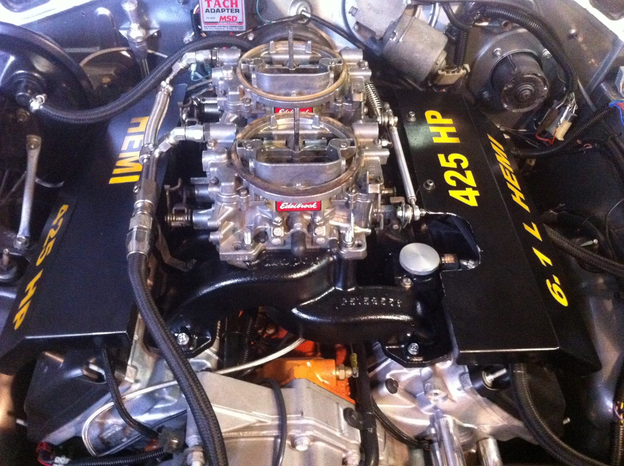
Ok...first notes:
Tuning.
Idle was about the same AF - with similar vacuum of around 18"
Cruise needed to be leaned out one step on the rods
Primaries power stage needing leaning one step on the rods
Secondary jets needed leaning one or two stages - will depend on weather (082 to .080/.077)
Pump shot backed off to second hole indicates most constant mixture at launch on gauge
Observations
Most obvious was the much smoother idle...even the wife commented that it sounded less 'spitty'
Second is that the 'light switch' issue where it suddenly came on at around 2500 with the Modman has disappeared completely - there is a completely smooth torque curve from idle to 6800rpm
Car is noticeably quicker when transitioning from cruise to WOT in top gear - the change in diff ratio obviously helps...but again it feels like it comes 'on song' straight away...no 'sogginess' or lag.
The induction noise sounds completely different....and SO MUCH BETTER - sounds much more like the old Thermoquad 'roar'..I wont have any track results for a few mths.....but Im completely confident my 60 ft times will be better as it responds so much more sharply than before.
Last edited by Moparmal; 03/07/15 04:58 AM.
67 RO23 clone with 6.1 SRT Hemi and dual quads. Soon to have Drag Pak induction and Throttle body.
|
|
|
Re: New Eddy dual quad vs old DQ Modman - first notes
[Re: Moparmal]
#1370146
03/07/15 05:43 PM
03/07/15 05:43 PM
|
Joined: Feb 2011
Posts: 4,302
Nebraska
72Swinger
master
|
master
Joined: Feb 2011
Posts: 4,302
Nebraska
|
Been considering a 392 cam for wifes Charger to keep MDS and the 28mpg the thing is capable of right now.
Mopar to the bone!!!
|
|
|
Re: New Eddy dual quad vs old DQ Modman - first notes
[Re: 72Swinger]
#1370147
03/07/15 07:39 PM
03/07/15 07:39 PM
|
Joined: Feb 2007
Posts: 72
San Angelo, Texas
Cevidicus
member
|
member
Joined: Feb 2007
Posts: 72
San Angelo, Texas
|
Quote:
Been considering a 392 cam for wifes Charger to keep MDS and the 28mpg the thing is capable of right now.
That's what I'll be running in my vvt 5.7. I've read all kinds of comments and outcomes from using that cam. From zero hp gain to 60rwhp(which I've never seen duplicated). Most seem to get about 20-30 rwhp out of it. That's with pretty much no gains until 4000rpm. Then it kicks in. Also those with gains don't seem to be using the phaser limiters. Several that did did not show any gains. I bought mine for 55 3 years ago. But they have gone up. Still needs a good set of springs.
|
|
|
Re: New Eddy dual quad vs old DQ Modman - first notes
[Re: Moparmal]
#1370149
03/08/15 04:55 PM
03/08/15 04:55 PM
|
Joined: Jan 2008
Posts: 4,255
Canada
WO23Coronet
master
|
master
Joined: Jan 2008
Posts: 4,255
Canada
|
Quote:
Ok...first notes:
Tuning.
Idle was about the same AF - with similar vacuum of around 18"
Cruise needed to be leaned out one step on the rods
Primaries power stage needing leaning one step on the rods
Secondary jets needed leaning one or two stages - will depend on weather (082 to .080/.077)
Pump shot backed off to second hole indicates most constant mixture at launch on gauge
Observations
Most obvious was the much smoother idle...even the wife commented that it sounded less 'spitty'
Second is that the 'light switch' issue where it suddenly came on at around 2500 with the Modman has disappeared completely - there is a completely smooth torque curve from idle to 6800rpm
Car is noticeably quicker when transitioning from cruise to WOT in top gear - the change in diff ratio obviously helps...but again it feels like it comes 'on song' straight away...no 'sogginess' or lag.
The induction noise sounds completely different....and SO MUCH BETTER - sounds much more like the old Thermoquad 'roar'..I wont have any track results for a few mths.....but Im completely confident my 60 ft times will be better as it responds so much more sharply than before.
Does that intake have a 6.1 port window or an early 5.7 one?
|
|
|
|
|


