 Please explain these ignition switch positions to me
#1665920
Please explain these ignition switch positions to me
#1665920
08/31/14 05:35 PM
08/31/14 05:35 PM
|
Joined: Aug 2003
Posts: 18,575
Dreaming of the 808
AZ_A12_BEE
 OP
OP
I Live Here
|
OP
I Live Here
Joined: Aug 2003
Posts: 18,575
Dreaming of the 808
|
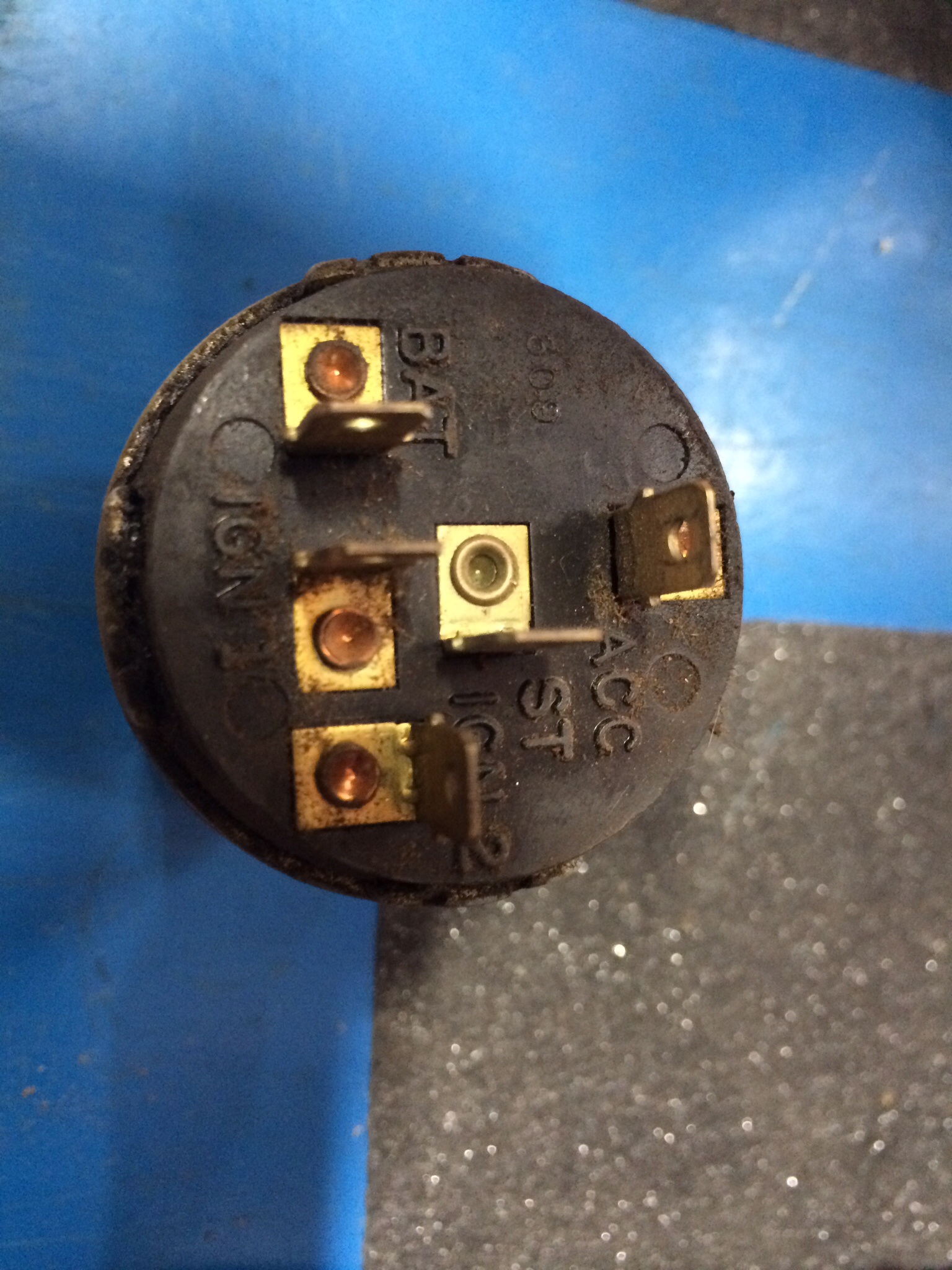
I think I understand a few
BAT, battery power to switch
ACC- accessories hot when key is turned to left
ST, start, monetary power to starter as long as key is in that starting position all the way to right
IGN1, is this the run position after the key moves left after starting?
IGN2- not sure what this is, is it the same as IGN1?
69.5 A12 Bee, first purchased in 1976, car 169 on registry
69 Coronet R/T 440/4 spd
69 Coronet 500 Conv H code 383 4bbl/auto
37 Plymouth PU
Find your spot on earth and ride it.
|
|
|
Re: Please explain these ignition switch positions to me
[Re: RapidRobert]
#1665923
08/31/14 08:49 PM
08/31/14 08:49 PM
|
Joined: Jan 2003
Posts: 27,421
Balt. Md
383man
Too Many Posts
|
Too Many Posts
Joined: Jan 2003
Posts: 27,421
Balt. Md
|
Quote:
Quote:
IGN2- not sure what this is, is it the same as IGN1?
no, it sends fire directly to the coil positive primary terminal when starting, bypassing the ballast that the current has to go thru in ign1 (run). This terminal is energized at the same time as the "ST" start ign switch terminal which feeds the yellow wire to the "ign" terminal on the starter relay. These have to be seperate (not connected to each other) terminals on the ign switch otherwise current would feedback from the coil to the ign switch to the starter relay yellow wire "ign" terminal which might keep the starter solenoid partly or wholly engaged at all times as opposed to just when starting & one of our left coast members just had a problem with that cuz the "awesome  wiring diagram" in the archives improperly shows the yellow starter relay wire being connected to the ballast/coil. The seperate ign2 "full voltage" and ST "start" terminals on the ign sw are either both hot (when cranking) or both dead (in ign1 run) wiring diagram" in the archives improperly shows the yellow starter relay wire being connected to the ballast/coil. The seperate ign2 "full voltage" and ST "start" terminals on the ign sw are either both hot (when cranking) or both dead (in ign1 run)
That is right. Ign-1 is key on power like to the ballast and alt field. Ign-2 and ST both get the power in the start position as was said and as was also said they cannot be hooked together as when the key would be turned to the on (ign-1) the ign-1 power would go through the ballast and then backfeed to the starter relay and if enough volts get through the ballast to work the starter relay it would crank in the run posistion. I know as years ago I had an old ign switch and tried it as it was a Ford switch and had no ign-2 on it since Ford bypasses its primary resistor wire with the starter solenoid. Ron
|
|
|
Re: Please explain these ignition switch positions to me
[Re: AZ_A12_BEE]
#1665925
09/01/14 04:47 AM
09/01/14 04:47 AM
|
Joined: Mar 2003
Posts: 4,848
Memphis
HemiRick
master
|
master
Joined: Mar 2003
Posts: 4,848
Memphis
|
Fords have a resistance wire that powers the coil...and lowers the voltage..
Take care,
Rick
68 Coronet R/T 440 & 68 Charger 528 Hemi,and 5 Challengers! 6 cyl, 318, 360, 383, 451
|
|
|
Re: Please explain these ignition switch positions to me
[Re: AZ_A12_BEE]
#1665927
09/01/14 02:44 PM
09/01/14 02:44 PM
|
Joined: Aug 2007
Posts: 6,095
Valencia, España
NachoRT74
master
|
master
Joined: Aug 2007
Posts: 6,095
Valencia, España
|
Quote:
I think I understand a few
BAT, battery power to switch
ACC- accessories hot when key is turned to left
ST, start, monetary power to starter as long as key is in that starting position all the way to right
IGN1, is this the run position after the key moves left after starting?
IGN2- not sure what this is, is it the same as IGN1?
Batt... input, Red wire. comes from alt wire main splice
Acc... Black wire. feeds out accesories just in RUN ( Ign 1 ) position, and Acc position ( when its available ). Runs to fuse box
St... Start Position, yellow wire. Runs straight to starter relay, no other splice. Works in Ign 2 position, cranking
Ign1... Its acually the RUN position. Blue wire. Feeds just in RUN of course. All engine sources ( ballast, reg, ECU if pressent ) and some stuff into the cab ( cluster brake light, sometimes voltage limiter ) is sourced from here.
Ign2... Start Position. Brown wire. Bypass the ballast to feed the full 12 volts at this moment. No splices around, just the ballast splice into the coil wire to bypass the ballast.
NOTE:
when ballast is conected, both Ign wires are hot, just with diff voltages on different stances, meaning with this:
In RUN... Ign 1 is full 12 volts and Ign 2 is getting back the power throught ballast, so anything between 5-9 volts can be there.
In START... Ign 2 is full 12 volts, and Ign 1 is getting power back through the ballast, so anything between 5-9 volts can be there.
For this reason is why you see the cluster brake light dimming when cranking
TO TEST THE IGN SWITCH RIGHT OUT THE PRONGS:
One tester lead allways on BATT
Ign 1 and ACC will get continuity with BATT prong on first switch position
Ign 2 and Starter will get continuity with BATT prong on second ign switch position ( the one being pushed ).
Acc will get also continuity with BATT on ACC position.
ANY OTHER continuity test will get you no continuity reading
With a Charger born in Chrysler assembly plant in Valencia, Venezuela
|
|
|
Re: Please explain these ignition switch positions to me
[Re: 383man]
#1665929
09/01/14 08:58 PM
09/01/14 08:58 PM
|
Joined: Aug 2003
Posts: 18,575
Dreaming of the 808
AZ_A12_BEE
OP
I Live Here
|
OP
I Live Here
Joined: Aug 2003
Posts: 18,575
Dreaming of the 808
|
Quote:
Quote:
Quote:
Quote:
Quote:
IGN2- not sure what this is, is it the same as IGN1?
no, it sends fire directly to the coil positive primary terminal when starting, bypassing the ballast that the current has to go thru in ign1 (run). This terminal is energized at the same time as the "ST" start ign switch terminal which feeds the yellow wire to the "ign" terminal on the starter relay. These have to be seperate (not connected to each other) terminals on the ign switch otherwise current would feedback from the coil to the ign switch to the starter relay yellow wire "ign" terminal which might keep the starter solenoid partly or wholly engaged at all times as opposed to just when starting & one of our left coast members just had a problem with that cuz the "awesome wiring diagram" in the archives improperly shows the yellow starter relay wire being connected to the ballast/coil. The seperate ign2 "full voltage" and ST "start" terminals on the ign sw are either both hot (when cranking) or both dead (in ign1 run)
That is right. Ign-1 is key on power like to the ballast and alt field. Ign-2 and ST both get the power in the start position as was said and as was also said they cannot be hooked together as when the key would be turned to the on (ign-1) the ign-1 power would go through the ballast and then backfeed to the starter relay and if enough volts get through the ballast to work the starter relay it would crank in the run posistion. I know as years ago I had an old ign switch and tried it as it was a Ford switch and had no ign-2 on it since Ford bypasses its primary resistor wire with the starter solenoid. Ron
I'm rewiring the Ford 302 in my 37 pickup, are you saying that Fords don't need Ign-2, only Ign-1? Do Fords even need a ballast resistor with a points distributor ?
Yes. Most Fords use a magnetic pole starter that has no solenoid on the starter as they use one of the field pole magnets to pull the starter drive into the flywheel and they use the small Ford type starter solenoid on the fenderwell. You know as it has the pos battery cable to one side and the other cable goes to the starter. Then it has to small terminals as one is marked (S) and it is from the ign switch and NSS to work the solenoid in the start position. The other small terminal is marked (I) and it has a small contact finger in there that the solenoid contact hits while cranking and it sends 12 volts to the coil bypassing the Ford resistor wire which is part of the primary wire harness between the ign switch and the coil. Sure you could use the Mopar ign switch with the ign-2 terminal but you dont need it on that type of Ford system so if you wanted to use the Mopar ign switch you just dont have to hook anything up to the ign-2 terminal. Ford did use a resistance in their point ign systems as it was a resistance wire in the wire harness to the coil primary pos side that basically does the same as the Mopar ballast resistor but I dont believe the wire type resistor changes some with heat like the Mopar ballast. Ron
Ron, can I use a generic ignition switch with just Bat, Start and Ign1 and make this work with the Ford 302? Do I still need a ballast resistor before the coil? It has no resistor wire since this is home made stuff.
Last edited by AZ_A12_BEE; 09/01/14 09:01 PM.
69.5 A12 Bee, first purchased in 1976, car 169 on registry
69 Coronet R/T 440/4 spd
69 Coronet 500 Conv H code 383 4bbl/auto
37 Plymouth PU
Find your spot on earth and ride it.
|
|
|
Re: Please explain these ignition switch positions to me
[Re: AZ_A12_BEE]
#1665930
09/02/14 12:30 AM
09/02/14 12:30 AM
|
Joined: Nov 2003
Posts: 10,693
Surface of the Sun, AZ
Hotwheelsjr
I Live Here
|
I Live Here
Joined: Nov 2003
Posts: 10,693
Surface of the Sun, AZ
|
Quote:
Quote:
Quote:
Quote:
Quote:
Quote:
IGN2- not sure what this is, is it the same as IGN1?
no, it sends fire directly to the coil positive primary terminal when starting, bypassing the ballast that the current has to go thru in ign1 (run). This terminal is energized at the same time as the "ST" start ign switch terminal which feeds the yellow wire to the "ign" terminal on the starter relay. These have to be seperate (not connected to each other) terminals on the ign switch otherwise current would feedback from the coil to the ign switch to the starter relay yellow wire "ign" terminal which might keep the starter solenoid partly or wholly engaged at all times as opposed to just when starting & one of our left coast members just had a problem with that cuz the "awesome wiring diagram" in the archives improperly shows the yellow starter relay wire being connected to the ballast/coil. The seperate ign2 "full voltage" and ST "start" terminals on the ign sw are either both hot (when cranking) or both dead (in ign1 run)
That is right. Ign-1 is key on power like to the ballast and alt field. Ign-2 and ST both get the power in the start position as was said and as was also said they cannot be hooked together as when the key would be turned to the on (ign-1) the ign-1 power would go through the ballast and then backfeed to the starter relay and if enough volts get through the ballast to work the starter relay it would crank in the run posistion. I know as years ago I had an old ign switch and tried it as it was a Ford switch and had no ign-2 on it since Ford bypasses its primary resistor wire with the starter solenoid. Ron
I'm rewiring the Ford 302 in my 37 pickup, are you saying that Fords don't need Ign-2, only Ign-1? Do Fords even need a ballast resistor with a points distributor ?
Yes. Most Fords use a magnetic pole starter that has no solenoid on the starter as they use one of the field pole magnets to pull the starter drive into the flywheel and they use the small Ford type starter solenoid on the fenderwell. You know as it has the pos battery cable to one side and the other cable goes to the starter. Then it has to small terminals as one is marked (S) and it is from the ign switch and NSS to work the solenoid in the start position. The other small terminal is marked (I) and it has a small contact finger in there that the solenoid contact hits while cranking and it sends 12 volts to the coil bypassing the Ford resistor wire which is part of the primary wire harness between the ign switch and the coil. Sure you could use the Mopar ign switch with the ign-2 terminal but you dont need it on that type of Ford system so if you wanted to use the Mopar ign switch you just dont have to hook anything up to the ign-2 terminal. Ford did use a resistance in their point ign systems as it was a resistance wire in the wire harness to the coil primary pos side that basically does the same as the Mopar ballast resistor but I dont believe the wire type resistor changes some with heat like the Mopar ballast. Ron
Ron, can I use a generic ignition switch with just Bat, Start and Ign1 and make this work with the Ford 302? Do I still need a ballast resistor before the coil? It has no resistor wire since this is home made stuff.
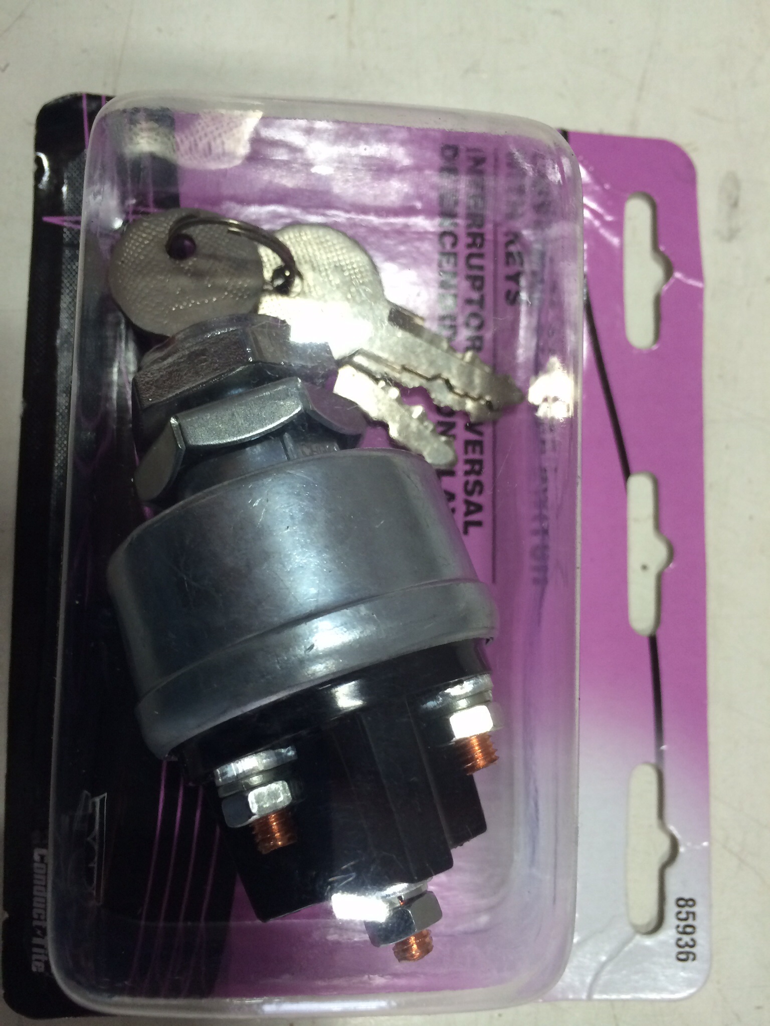
That exact switch is all I run in my Rat. And why stay points? Get rid of that POS and go elec.
|
|
|
Re: Please explain these ignition switch positions to me
[Re: Hotwheelsjr]
#1665931
09/02/14 12:53 AM
09/02/14 12:53 AM
|
Joined: Aug 2003
Posts: 18,575
Dreaming of the 808
AZ_A12_BEE
OP
I Live Here
|
OP
I Live Here
Joined: Aug 2003
Posts: 18,575
Dreaming of the 808
|
Quote:
Quote:
Quote:
Quote:
Quote:
Quote:
Quote:
IGN2- not sure what this is, is it the same as IGN1?
no, it sends fire directly to the coil positive primary terminal when starting, bypassing the ballast that the current has to go thru in ign1 (run). This terminal is energized at the same time as the "ST" start ign switch terminal which feeds the yellow wire to the "ign" terminal on the starter relay. These have to be seperate (not connected to each other) terminals on the ign switch otherwise current would feedback from the coil to the ign switch to the starter relay yellow wire "ign" terminal which might keep the starter solenoid partly or wholly engaged at all times as opposed to just when starting & one of our left coast members just had a problem with that cuz the "awesome wiring diagram" in the archives improperly shows the yellow starter relay wire being connected to the ballast/coil. The seperate ign2 "full voltage" and ST "start" terminals on the ign sw are either both hot (when cranking) or both dead (in ign1 run)
That is right. Ign-1 is key on power like to the ballast and alt field. Ign-2 and ST both get the power in the start position as was said and as was also said they cannot be hooked together as when the key would be turned to the on (ign-1) the ign-1 power would go through the ballast and then backfeed to the starter relay and if enough volts get through the ballast to work the starter relay it would crank in the run posistion. I know as years ago I had an old ign switch and tried it as it was a Ford switch and had no ign-2 on it since Ford bypasses its primary resistor wire with the starter solenoid. Ron
I'm rewiring the Ford 302 in my 37 pickup, are you saying that Fords don't need Ign-2, only Ign-1? Do Fords even need a ballast resistor with a points distributor ?
Yes. Most Fords use a magnetic pole starter that has no solenoid on the starter as they use one of the field pole magnets to pull the starter drive into the flywheel and they use the small Ford type starter solenoid on the fenderwell. You know as it has the pos battery cable to one side and the other cable goes to the starter. Then it has to small terminals as one is marked (S) and it is from the ign switch and NSS to work the solenoid in the start position. The other small terminal is marked (I) and it has a small contact finger in there that the solenoid contact hits while cranking and it sends 12 volts to the coil bypassing the Ford resistor wire which is part of the primary wire harness between the ign switch and the coil. Sure you could use the Mopar ign switch with the ign-2 terminal but you dont need it on that type of Ford system so if you wanted to use the Mopar ign switch you just dont have to hook anything up to the ign-2 terminal. Ford did use a resistance in their point ign systems as it was a resistance wire in the wire harness to the coil primary pos side that basically does the same as the Mopar ballast resistor but I dont believe the wire type resistor changes some with heat like the Mopar ballast. Ron
Ron, can I use a generic ignition switch with just Bat, Start and Ign1 and make this work with the Ford 302? Do I still need a ballast resistor before the coil? It has no resistor wire since this is home made stuff.
That exact switch is all I run in my Rat. And why stay points? Get rid of that POS and go elec.
Why? It's simple and it runs, besides I would have to buy an electronic ignition, I'm cheap remember 
69.5 A12 Bee, first purchased in 1976, car 169 on registry
69 Coronet R/T 440/4 spd
69 Coronet 500 Conv H code 383 4bbl/auto
37 Plymouth PU
Find your spot on earth and ride it.
|
|
|
Re: Please explain these ignition switch positions to me
[Re: AZ_A12_BEE]
#1665933
09/02/14 03:23 AM
09/02/14 03:23 AM
|
Joined: Dec 2003
Posts: 16,844
Phoenix - surface of the sun
nomore65BelvJim
I Live Here
|
I Live Here
Joined: Dec 2003
Posts: 16,844
Phoenix - surface of the sun
|
Quote:
Quote:
That exact switch is all I run in my Rat. And why stay points? Get rid of that POS and go elec.
Why? It's simple and it runs, besides I would have to buy an electronic ignition, I'm cheap remember
Me too  but here's one that even I think is very reasonable! but here's one that even I think is very reasonable! 
302 electronic dist
|
|
|
Re: Please explain these ignition switch positions to me
[Re: nomore65BelvJim]
#1665936
09/03/14 01:32 PM
09/03/14 01:32 PM
|
Joined: Jan 2005
Posts: 43
1974Cuda360
member
|
member
Joined: Jan 2005
Posts: 43
|
This is a very informative thread, and it explains an ignition/starter issue that I've been dealing with for years. I switched to an electronic fuel injection setup on my Cuda years ago, and the engine does not start with the ignition key. When I crank the ignition with the key, the starter engages, but the engine won't fire.
This is because when the key is turned to the on position (IGN 1), 12 V goes to the computer system, MSD ignition and fuel pump. But, when the key is in the start position for the starter to engage, voltage drops to the computer, MSD ignition and fuel pump, thus preventing the engine from starting.
To solve the problem, I installed an ignition button that runs directly to the starter relay. But, I prefer to wire everything to start with the ignition key.
If I am not running a ballast resistor, can I join the (IGN 1) and (IGN 2) wires together so that I'm getting a constant 12 V to the computer, MSD ignition and fuel pump while the starter is engaging?
Any input or suggestions are highly appreciated. This issue has been bugging me for years, and I just want my car to start with the ignition key like all other vehicles.
Last edited by 1974Cuda360; 09/03/14 01:35 PM.
|
|
|
Re: Please explain these ignition switch positions to me
[Re: 1974Cuda360]
#1665937
09/03/14 03:08 PM
09/03/14 03:08 PM
|
Joined: Aug 2007
Posts: 6,095
Valencia, España
NachoRT74
master
|
master
Joined: Aug 2007
Posts: 6,095
Valencia, España
|
Quote:
To solve the problem, I installed an ignition button that runs directly to the starter relay. But, I prefer to wire everything to start with the ignition key.
on post 76 Mopars thats the way they did it, saving one wire from ign key but using a diff starter relay with dual prongs hooked to the starter position, ONE OF THEM isolated from it on RUn position, because if not, it will keep cranking once the key is in Run from the bypass ballast wire, through ballast.
Quote:
If I am not running a ballast resistor, can I join the (IGN 1) and (IGN 2) wires together so that I'm getting a constant 12 V to the computer, MSD ignition and fuel pump while the starter is engaging?
You don't need to remove the ballast. Simply splice the coil wire straight to the MSD module red wire ( the thin one, not the thick one )
The thin red wire is used as trigger to turn it ON, not to feed the MSD. So the voltage coming from ballas is enough to keep it ON
However if you want to remove the ballast, yes, will need to splice brown and blue wires coming from igng switch to splice it into the thin red wire.
HOWEVER ( once again ) if you want to keep somehow the stock look with the ballast, or make it easier to get it back to stock and you are unsure about keep the ballast or not due the low voltage coming from resistor, you can also remove the resistor from back of the ceramic piece, and splice in it a jumper wire. This will hide the instant "splice" of the RUN and Start circuit into the ceramic and will keep conecting this piece like stock, without deal with hack up the wiring.
To feed the fuel pump, please use a relay. You still can trigger it from same wire as the MSD
With a Charger born in Chrysler assembly plant in Valencia, Venezuela
|
|
|
Re: Please explain these ignition switch positions to me
[Re: 71ChargerSE]
#1665939
09/04/14 02:22 AM
09/04/14 02:22 AM
|
Joined: Aug 2007
Posts: 6,095
Valencia, España
NachoRT74
master
|
master
Joined: Aug 2007
Posts: 6,095
Valencia, España
|
weird!!! something is wrong there! It shouldn't as far I know.
but to be specific to the question... IF THAT CASE IS FOR REAL, not on a plug and play job. Would requiere to get a later starter relay to get the source for the ballast bypass. If you use your existant setup, the starter will never disengage. Will keep cranking being sourced from the RUN circuit coming from ballast.
ALTHOUGHT, I would fit the correct ign switch.
With a Charger born in Chrysler assembly plant in Valencia, Venezuela
|
|
|
|
|


