|
 Re: Pistons
[Re: onig]
#1370113
Re: Pistons
[Re: onig]
#1370113
12/21/14 05:47 PM
12/21/14 05:47 PM
|
Joined: Feb 2011
Posts: 4,302
Nebraska
72Swinger

master
|
master
Joined: Feb 2011
Posts: 4,302
Nebraska
|
Full ported 6.1 intake weighs 34 lbs without TB,rails or injectors.
Mopar to the bone!!!
|
|
|
Re: Hemi
[Re: SRT440DUSTER]
#1370115
12/29/14 06:56 PM
12/29/14 06:56 PM
|
Joined: Aug 2003
Posts: 3,101
cincinnati ohio
mcat4321
master
|
master
Joined: Aug 2003
Posts: 3,101
cincinnati ohio
|
Quote:
What does it take to run eagle heads on a stock bottom 6.1. With them being closed chamber I've read it takes compression to 11.3 to 1. I believe stock 6.1 is 10.5 to 1. Wondering how much of a gain. I have a set of both 6.1s and eagles ready to be sent out for cnc machining. Wondering if I can gain a worthy amount putting ported eagles on vs the 6.1s. I see the flow very similar numbers. But the added compression should add some power. No?
FYI eagle's require longer push rods and different valve covers. 
|
|
|
Re: Hemi
[Re: SRT440DUSTER]
#1370117
12/29/14 08:36 PM
12/29/14 08:36 PM
|
Joined: Aug 2003
Posts: 3,101
cincinnati ohio
mcat4321
master
|
master
Joined: Aug 2003
Posts: 3,101
cincinnati ohio
|
Quote:
Thanks I picked up a complete vvt 5.7 throttle body to pan for 150 bucks with a spun rod bearing. So I have everything from that. Would the pushrods be correct from that engine? Or would it be custom length?
i do not know. i had an early 5.7 with eagles,that took custom PR's.. the 6.1 are different yet. personally i would go with the 6.1 heads, they have better lighter valves
|
|
|
 Re: Gen III Hemi, please post things to avoid and know..
[Re: gregsdart]
#1370120
Re: Gen III Hemi, please post things to avoid and know..
[Re: gregsdart]
#1370120
01/15/15 05:58 AM
01/15/15 05:58 AM
|
Joined: May 2007
Posts: 553
Sac, CA, USA
ntstlgl1970
mopar
|
mopar
Joined: May 2007
Posts: 553
Sac, CA, USA
|
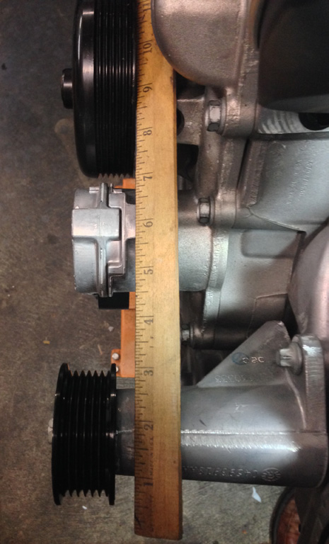
Using the P/S pump eliminator idler pulley/bracket (2013 models) with 6.1 heads, the idler pulley sits about 3/8" too far forward. Maybe the Apache or Eagle heads changed the mounting boss height. Guess i'll be breaking out the welder....
If you have an early block that uses SAE thread oil filters, using a jeep angled oil filter adapter uses metric filters.
Was hoping to bypass the A/C compressor with just the P/S eliminator bracket/pulley, but the belt will interfere with the belt tensioner.
Last edited by ntstlgl1970; 01/15/15 06:08 AM.
|
|
|
Re: Gen III Hemi, please post things to avoid and know..
[Re: ntstlgl1970]
#1370121
01/15/15 03:49 PM
01/15/15 03:49 PM
|
Joined: Aug 2003
Posts: 3,101
cincinnati ohio
mcat4321
master
|
master
Joined: Aug 2003
Posts: 3,101
cincinnati ohio
|
Quote:
Using the P/S pump eliminator idler pulley/bracket (2013 models) with 6.1 heads, the idler pulley sits about 3/8" too far forward. Maybe the Apache or Eagle heads changed the mounting boss height. Guess i'll be breaking out the welder....
If you have an early block that uses SAE thread oil filters, using a jeep angled oil filter adapter uses metric filters.
Was hoping to bypass the A/C compressor with just the P/S eliminator bracket/pulley, but the belt will interfere with the belt tensioner.
this is because the the delete pulley is designed for vvt engines that use a different timing cover to clear the longer cam... i machined mine down on the pulley end, with no issue..
|
|
|
Re: Pistons
[Re: MR_P_BODY]
#1370122
01/29/15 09:46 AM
01/29/15 09:46 AM
|
Joined: Jan 2003
Posts: 9,986
Frostbitefalls MN (Rocky&Bullw...
gregsdart
 OP
OP
master
|
OP
master
Joined: Jan 2003
Posts: 9,986
Frostbitefalls MN (Rocky&Bullw...
|
Quote:
Quote:
Quote:
Quote:
Wish someone would make a plastic 6.1 intake. They are heavy, although I put the time in to lighten mine quite a bit. 6.4 intakes have been swapped onto 6.1's and 5.7's both. Modern Muscle even offers CNC of the TB opening.
Will the 6.4 intake fit a 5.7

With Eagle,6.1 or Apache heads, yes.
Ok
There is one fitment issue for the 6.4 VR manifold on an early 5.7 or 6.1 block. The intake manifold hits at the water passage area at the front of the block, and may also have problems with the water tubes that run across the top of the block.
I pirated some info from another forum with some info on the fix. Basically grind off the webbing where the interference is, then heat and bend the plastic a bit, putting a small dent in the offending runner for clearance. I plan to grind the block casting some to keep the dent to a minimum. Another option would be some grinding and a spacer for the manifold. Here is some info on controlling the runners also. http://www.lxforums.com/board/showthread.php/266543-2011-Variable-Runner-Intake-Manifold
The Part Numbers
Intake manifold P/N (includes all gasket, O-rings, mounting bolts): 68090674AA
SRV (short runner valve) actuator P/N: 5038529AA
Actuator bolts (3 required) P/N: 6509377AA
Pigtail connector: 1-68064996AA
Update 2011-05-19:
After testing the OEM actuator using a signal generator to simulate rpm and a digital oscilloscope to monitor pin 3 / 4 outputs, it became clear that readily available rpm switches used to control nitrous or transmission shift events would be ideal to control actuation at any rpm set-point.
When the actuator is first powered up, similar to the throttle body the actuator goes through one open / close cycle to confirm proper operation. NOTE: trying to make the actuator operate without a load (the manifold's actuator rods / valves) will result in irratic operation, or no movement at all.
Connectorship
I advise buying the proper pigtail / connector (1 of 68064996AA) from any number of OEM outlets. If you elect to forgo the connector, pin 1 is on the left as you are looking at the pins inside the (male) connector housing on the actuator with the driveshaft pointing downward. See the pigtail connector diagram below from Chrysler (the numbers 1 and 4 are cast into the pigtail connector housing). Below is the pin-out and connection protocol:
Pin 1: B+, switched (attach to a switched 12V source)
Pin 2: B- (attach to chassis ground)
Pin 3: signal, logic level (negative going)
Pin 4: signal, logic level, no connection (can be used to activate an annunciator)
Actuator Operation
Pins 3 and 4 of the actuator use logic-level (0 or 5V reference) protocol to initiate (pin 3 � shorted to ground) and confirm (pin 4 � logic low during short runner mode). Both pins I/O are low impendence. Pin 4 requires no connection, but must not short to ground GND or power B+.
Note: pin 4 sits a ~6.5VDC and goes low allowing the PCM to confirm proper operation of the actuator when the valves open. A typical 5mm LED (including blue) can be forward-biased (activated) by connecting the negative lead to pin 4 and the positive to pin 3. This would provide a visual aid to display the actuator has PWR, and when exceeding the rpm set-point (and valves open) the LED will turn off.
For an LED to activate above the set-point will require a small logic circuit to supply regulated current (in this case from B+) when the pin4 go low (at some point I�ll try and find an off-the-shelf a logic / driver module that makes it simpler for folks to install).
FYI; maximum current consumption during transition is ~2.6A. Steady-state (open or closed) is ~2-300mA.
The Set-point
Although the SRV system on the 392 HEMI�s transitions from long runner to short runner mode between 4800 and 4900rpm, this may vary a bit when the SRV system is mounted on other engine profiles. The best method of determining where to set rpm threshold will be to dyno in long runner mode to redline, then short runner mode. After a few pulls, compare the files looking for where they cross.
Something worth observing and discussing will be whether to make the rpm set-point value above to below the actual crossover point. It will be clear with different engine configurations the area under the curves will either drop off more rapidly, or gain more rapidly in one mode or the other. For example, if your engine�s global TQ gains are reducing quickly in long runner mode approaching the cross over, while in short runner mode it appears more area is under the curve just past to the crossover point, it would be prudent to lower the set-point to allow short runner mode to produce those gains at an earlier rpm.
Another thought is whether to use the individual TQ or HP areas under the curve to determine the set-point. IMO where this will come into play is on the strip where shift points occur and the resulting next-gear rpm commences.
UPDATE, 2015-01-26;
It's become evident across a number of different platforms that 4800rpm +50 is the set point. I originally thought larger displacement engines would need to have a lower set point given extra air flow. Ut seeing how more and more engines of differing displacements are also settling in around, if not right on, 4800rpm, something else is the main driver.
It's rather simple; for any given rpm, the rate at which the intake valves stop and start airflow within the runners is the same for any engine no matter what the engine displacement. It is this act that leads to runner length resonance being directly related to rpm - and not displacement.
In simple terms(?); the act of pumping more air (tuned resonance) into the combustion chambers during the intake stroke than would normally enter depends on what rpm is present to produce the reverse wavelengths, otherwise known as Helmholtz effect. This is precisely the same function long tube headers provide to extract more spent exhaust gasses out of the combustion chamber.
Update 2012-10-24:
After testing a number of rpm switches on the vehicle, it became evident EMI / RFI noise was gong to be an issue. Proper filtering of the incoming rpm signal, along with a normally open (NO) trigger, and receive rpm signal from either an injector or coil pack B- was essential. The most reliable rpm output turned out to be a primary winding feed to B- for the coils. To determine this I used my digital oscilloscope connected with with the scope riding on the front windshield and an RS232 cable running into the vehicle to allow logging to a laptop. This was a PITA as I needed to run 110AC out to the scope from a 12V invertor, but the results were definitely worth it. An appropriate window switch must have a normally open (NO) output that shorts to ground (GND) when the desired rpm threshold set point is crossed.
The MSD Ignition 8969, digital RPM window switch (http://www.summitracing.com/parts/msd-8969) took the lead and never gave it up throughout testing. Here's the connection map;
- Connect white lead to a negative coil lead at injector (all injectors across all platforms will have one color-coded lead in common - this is GND)
- Use yellow lead to trigger SRV actuator's pin3
- Configure the MSD controller for single cylinder operation (there are eight coils, so you want the unit to recognize single cylinder operation)
- Initially configure opening setpoint to 4800rpm (factory 392) until you can dyno in either mode to find crossover
Pigtail (OEM) Connector PN / pinout (note you are looking into the connector body in this pic, pin 1 and 4 are molded into housing):
UPDATE: 2013-01-13;
Last edited by gregsdart; 01/29/15 10:07 AM.
|
|
|
Re: Gen III Hemi, please post things to avoid and know..
[Re: gregsdart]
#1370123
02/02/15 11:25 AM
02/02/15 11:25 AM
|
Joined: Jan 2003
Posts: 9,986
Frostbitefalls MN (Rocky&Bullw...
gregsdart
OP
master
|
OP
master
Joined: Jan 2003
Posts: 9,986
Frostbitefalls MN (Rocky&Bullw...
|
Throttle body selection info pirated from another forum!
An LX member sent me a message asking, �What size TB do I need?�, and I realized that there really wasn�t a clear answer to his question. Oversize TBs are readily available, but they don�t come with any sort of recommendations or technical info to help with the decision. The vendors that offer these things aren�t even providing actual flow numbers for their products. The lack of info has cause TB selection to be quite the debatable topic. Therefore, I�m going to attempt to make some sense of the matter with the aid of an ordinary scientific calculator, a few common formulas, and even a little geometry.
First, I�ll explain in detail how flow area of each TB will be established. We�ll essentially determine effective flow area for each TB we want to use in our calculations. We are going to look at 80mm, 85mm, and 90mm. First we figure the total area of the round �hole�. We, then subtract the area of the 10mm throttle shaft. To improve accuracy, we�ll multiply this area by a value for discharge coefficient (cd). A reliable source tells me a 90mm TB flows 1006cfm at 20�/H2O. We�ll use this info to get our �cd�, and assume that all TB sizes exhibit this value. The math���
(90mm / 25.4)^2 x pi / 4 = 9.86in^2 bore area
(90mm / 25.4) x (10mm / 25.4) = 1.395in^2 throttle blade area
9.86in^2 � 1.40in^2 = 8.46in^2 total area
calculating theoretical max cfm from area�..
(20in/H2O)^.5 x 66.2 = 296.1fps
9.86in^2 x 299.1fps / 2.4 = 1054cfm (theoretical max)
1006cfm / 1054cfm = .955 cd
8.46in^2 x .955cd = 8.08in^2 effective flow area
�.Calculating for the other two sizes gives us the following values for our three TB sizes�.
80mm = 6.26in^2
85mm = 7.14in^2
90mm = 8.08in^2
In order to calculate the TB size we need, we must figure how much air we are using. ? For this, we can use the infamous �carb sizing� formula.
Eq.1 cfm = (CID x RPM x VE%) / 3456
If we look at the term �cfm�, or ft^3/m, we see that it is the product of an area(ft^2) and a velocity(ft/m), resulting in a simple flow analysis equation that can help determine the size we nee, based off of flow area.
Flow (cfm) = Area(ft^2) x Velocity(ft/m)
...adding a constant to convert units�..
Eq.2 cfm = in^2 x fps / 2.4
So we now have a simple way to solve for TB size, based on area, given that we have values for velocity and cfm. We�ve already tackled cfm. So, how do we our velocity values? 4bbl carbs are typically flowed at 1.5 inches of Hg. However, unrestricted carbureted engines typically see 0.8-1.2 inches of Hg at peak power. We�ll use these values, multiplying by 13.61 to convert from Hg to H2O. To get our velocity, we�ll use a formula common to any head porters who uses a pitot probe. Here are the formulas in action�..
Eq.3 (in/Hg x 13.61)^.5 x 66.2 = Velocity (fps)
(0.8 x 13.61)^.5 x 66.2 = 218.4fps
(1.2 x 13.61)^.5 x 66.2 = 267.5fps
Let�s take a look at what the factory did. We�ll use 5400rpm for the 5.7L engine and 6200rpm for the 6.1L mill. Let�s also use 100% VE for stock performance of 345hp and 440hp, respectively. Using Eq.1�..
(345 x 5400 x 100%) / 3456 = 539cfm
(370 x 6200 x 100%) / 3456 = 664cfm
Now we calculate for area. We�re going to use 218.4fps for the 5.7L and 267.5fps for the 6.1L. I�m wondering if the same TB that was designed from scratch for the 5.7L engine was used on the 6.1L simply to satisfy the accounting department. Let�s use Eq.2 and see��.
539cfm x 2.4 / 218.4fps = 5.923in^2
664cfm x 2.4 / 267.5fps = 5.957in^2
�We can also work the math backwards, plugging in 6.26in^2 for the stock TB�.
539cfm x 2.4 / 6.26in^2 = 206.6fps
664cfm x 2.4 / 6.26in^2 = 254.6fps
It appears that the decision to use the same TB on both engines was, indeed, made by the accountants. It also appears that they left a bit of room for a few bolt-on performance mods. Most importantly, the factory engineers agree with our .8-1.2 �/Hg range. Feeling confident with the math, let�s run the numbers for our fellow LX member and make a recommendation. He has a 423 stroker with ported heads and a custom grind cam suited for a 3600 stall TC, 5600 hp peak and a 6400 shift point with excellent VE%. Calculating for 0.8 and 1.2, or 218.4fps and 267.5fps, respectively�.
(423 x 5600 x 116%)/3456 = 795cfm
754cfm x 2.4 / 218.4 = 8.73in^s
754cfm x 2.4 / 267.5 = 7.13in^2
That particular engine would need a full 85mm at minimum and could make use of a TB even larger than the 90mm piece. I wouldn�t even recommend one of the ported stock jobs for this particular application. The stock throttle blade diameter is still the restriction. Of course, with the 85mm and the 90mm being the same price, he might as well go for the 90mm and be done with it.
At this point, someone is thinking, �yeah, yeah, but how power is it worth? And for how much?� Well, the dyno numbers and e.t. slips speak for themselves. However, power is determined by the air MASS we move through the engine and effectively burn. So, I done a little research and found a formula that calculates air density, based on barometric pressure and temperature. If temperature and VE% stay the same, we should be able to calculate, with fair accuracy, the change in air mass, thus power output. If VE% changes, then the difference will be even greater, meaning that our calculation is on the conservative side. We�ll use 29.921 �/Hg for standard barometric pressure. Doing all the math for the stock 80mm TB and the 90mm piece, we get 1.56�/Hg and .945�/Hg, respectively. 80�F seems like a reasonable number for intake temp. The calculation�.
Eq.4 1.325 x (inches of Hg / (temp�F + 460)) = air density
1.325 x (29.921-1.56) / (80+460) = .0696lbs/ft^3
1.325 x (29.921-.945) / (80+460) = .0711lbs/ft^3
.0711 / .0696 = 1.02
So, we would have a difference in mass of 2%, and that same difference in output. But, remember, this is assuming that VE% remains constant. In reality, the smaller TB would, indeed, cause a restriction in flow and have an adverse effect on VE%, making the difference even greater. Also, we would incur additional pumping losses from running under greater vacuum.
Alas, we shall remain conservative and take a look at this 2% from a cost perspective. It just so happens that the guy with the 6.1L Super Stock football upgraded his mill with heads and a cam, only to capture the 6.1L modified football. $3200 worth of parts netted him 59hp, or an increase of 13%. Add another $1000 for installation, and we get $323 per 1% increase. Cast TBs can be had for $500, resulting in the upgrade cost of $250 per1% increase. This means that a 90mm TB would have a higher bang for buck value than even a head/cam swap on a 423 stroker. If VE% differs between the stock and 90mm, even the shiny billet TBs begin to have a favorable bang for buck value on this size engine.
It is kind of unfair to do all the work for one guy, and leave everyone else out. Therefore, I made a nifty excel sheet to calculate for the most common Gen III Hemi displacements. I used VE% of 110 for the chart, suggesting a fairly stout, efficient package. Here, for the first time ever, is a chart to help with TB selection, based on rpm.
Using the chart is simple. If peak power is higher than the rpm in the 1.2 �/Hg column, or peak torque is higher than the rpm in the 0.8�/Hg column, then you should really consider an upgrade. If peak power is higher than the rpm in the 0.8�/Hg column, or your shift point is is higher than the rpm in the 1.2�.Hg, an upgrade can be of benefit in an �max-effort� application, but isn�t absolutely necessary. I even included accompanying power outputs, so you can also make a selection based off of expected N/A power.
Throttle Body Selection Chart
-----------80mm ----------85mm ---------90mm
---------0.8-1.2"/Hg ----0.8-1.2"/Hg ----0.8-1.2"/Hg
345_____5190-6360_____5920-7250_____6700-8200
370_____4840-5930_____5520-6760_____6250-7650
392_____4570-5590_____5210-6380_____5900-7220
426_____4200-5150_____4790-5870_____5420-6640
440_____4070-4980_____4640-5680_____5250-6430
N/A hp____360-500_______440-580_______510-660
Now, let�s take a look for the forced induction guys. A lot of people seem to think that the blower cars could benefit from a larger TB even more than the N/A guys. Let�s take a look. I will be using some additional formulas, mainly intended to help with compressor selection. The main differences are in air density and temperature, although I�ll be looking at flow before the compressor, too, for those who are entertaining the idea of relocating the TB to this place. The standard �carb sizing� formula is used here as well, suggesting that the engine determines the actual volume of air that is moved. The compressor only changes density, by way of temperature and boost. We must find a way to determine the temp of the air going in the engine. To do this we first figure temp of the air exiting the compressor. Then, we use our intercooler efficiency to get the actual temp. Here are those formulas�.
Eq.5 (boost psi + 14.7) / 14.7 = pressure ratio
Eq.6 ((Inlet temp�F + 460) x (pressure ratio)^.283) - 460 � Inlet temp�F = Ideal temp�F rise
Eq.7 Ideal temp rise / adiabatic efficiency + Inlet temp�F = actual compressor outlet temp
Eq.8 -1 x ( intercooler(IC) efficiency x ( IC temp�F in � temp�F ambient) � IC temp�F in) = IC temp�F out
Eq.9 ( Inlet temp�F + 460) /( IC temp�F out + 460 ) x pressure ratio = Density ratio
Eq.10 Outlet cfm x Density ratio = Inlet cfm
Although these formulas have a variety of uses, we�re only interested in using them for TB selection. Looking at Eq.10, we see that the changes in boost pressure and temp, therefore air density, only changes the inlet cfm requirements. Outlet cfm remains the same and is cal�d, using Eq.1. This is good news for those who have their TB after the compressor, like the Procharger systems. Because of the increased �outlet� temperature, it gets even better. The higher temps raise the speed of sound. The higher �mach speed� makes the engine think everything is larger in size, and will literally move your power band up in rpms. In essence the same size TB, after the compressor, will support even more rpms when used with boost. Sticking with the �calculation� theme, here is a formula to estimate the effects�.
Eq.11 old rpm peak x ((outlet temp�F + 460) / (inlet temp�F + 460))^.5 = new rpm peak
We�ll use our friend�s 423 again for the example, adding 10 psi boost at 80�F ambient. We�ll also use 75% for both compressor adiabatic efficiency and IC efficiency.
(10 + 14.7) / 14.7 = 1.68 pressure ratio
(80+460) x (1.68)^.283 � 460 � 80 = 85�F ideal temp rise
85 / .75 + 80 = 193�F actual compressor outlet temp
-1 x ( .75 x (193-80)-193) = 108�F final temp out
(80 + 460)/(108 + 460) x 1.68 = 1.597 density ratio
5600 x ((108 + 460) / (80 + 460))^.5 = 5740 new rpm peak
5740 / 5600 x 1.597 = 1.636
�Or a 64% increase in output at approx. 150rpms higher with the exact same TB. What happens if we use a roots-type blower, or move the TB to the inlet side of the compressor? We can use our density ratio to figure this out, keeping in mind that the inlet side is still at ambient temp. Remember that demand was calc�d to be 795cfm�
795 outlet cfm x 1.64 = 1300 inlet cfm
Woah!!!! Vacuum at WOT just jumped to 2.5�/Hg with a 90mm TB. Relocating the TB to the front of the compressor would cause a huge restriction�.Unless you were to use two of them.
It is my hope that all of these equations and examples will help make sense of TB selection for a variety of applications, and helps to explain �why� the larger TBs work. I also hope that the readers of this write-up will become a little more knowledgeable about their hotrods and the parts they are purchasing for them. Most importantly, when someone asks about a 90mm TB, we�ll have some real info to go with all of our �marketing� claims.
8..603 156 mph best, 2905 lbs 549, indy 572-13, alky
|
|
|
Re: Pistons
[Re: gregsdart]
#1370126
02/18/15 12:19 PM
02/18/15 12:19 PM
|
Joined: Apr 2005
Posts: 935
Deland, Florida
biff426
super stock
|
super stock
Joined: Apr 2005
Posts: 935
Deland, Florida
|
Quote:
Check cam end play on any combo using a different or new cam that has not bee successfully run. Some aftermarket cams have too little end play, causing scoring and broken pins, bent valves.
Well upon further investigation it is not really a cam end play issue the problem is the snout of the cam is not long enough and when you torque the cam bolt it pinches the thrust plate between the face of the cam and the timing gear. It is tight enough to be a problem but not tight enough to "feel" tight when you spin the engine by hand when assembled but if you torque the gear on with no chain you can barely turn it. I think it is more a problem with the cam then the timing set.
|
|
|
Mod Man misery.........
[Re: ntstlgl1970]
#1370128
02/26/15 01:37 AM
02/26/15 01:37 AM
|
Joined: Jan 2003
Posts: 3,943
Melbourne.....Oz-land
Moparmal
master
|
master
Joined: Jan 2003
Posts: 3,943
Melbourne.....Oz-land
|
The following is a detailed chronology of my efforts to get the Indy Modman intake to work efficiently on my Gen 3 HEMI.
While I have never had any complaints about the finish or workmanship of this intake �the following experiences should serve as a caution anyone planning on using this intake for qtr mile racing.
All tuning changes were validated both on the same dyno and at the track in similar DA.
I have been tuning Carter and Edelbrock carbs for thirty years and am fully aware of the processes required in re-calibration and enhancements.
1st tune � Single 800CFM AVS Thunder carb
333 RWHP � 110.8 MPH � 12.4 sec qtr - 1.94 60ft
Comment - Lean bog very apparent on launch
2nd tune - Drilled pump shooter to .040th � 1.91 60ft
Comment � No bog if I rolled on the throttle, but sluggish response
3rd tune � Pro Systems 830 cfm � 50cc Primary pump shot, 30cc secondary
No dyno � 109.8 mph � 12.4 sec � 1.84 60ft
Comment � No bog but sluggish 60 ft
4th tune � Twin Edlebrock 500cfm Performer carbs � drilled shooters to .040th
No dyno � 111.1 mph � 12.39 sec - 1.91 60ft
Comment� Slight bog unless I rolled in the throttle...improved top end.
5th tune � Twin Edelbrocks with twin Brodix turtles inserted in plenum
Comment - No change
6th tune � Twin Edelbrocks with full height divider along length of plenum � increased initial timing from 15 to 21 deg .
348.7 RWHP � 114.3 MPH � 11.9 sec - 1.82 60ft
This has been the best result achieved. The 60 ft is still woeful for the mph and HP but the MPH jumped significantly.
NOTES
� Traction not a factor in any testing...simply not making enough initial torque to be a concern!
- No modification of air bleeds with Holley, just jetting.
- The Modman plenum volume results in a significant loss of signal and requires a MAMMOTH pump shot to overcome the overall plenum volume requirements.
- The full height divider I ran was also �� wide, serving to occupy some plenum space as well as improve the signal.
- The car 60 footed better when I rolled on the throttle than when I rugged it in every scenario.
- Stalling up had a negative effect � often resulting in a bigger bog. I have determined this was because stalling uses up some of the �tip in� travel hence a smaller pump shot.
- The cam I ran was a HR with [Email]219@.50[/Email] � It does not require a big converter , nor really high gears, so this was not contributing to the issue .
Summary
On the street, no one would ever guess that these issues were to arise at the track..until I did some street tuning on drag radials. It was only then I noticed the car struggled to turn the tyres on the street until tune #6.
This problem manifested even worse at the track.
I hope to be able to provide a comparative using the Edelbrock dual plane dual quad in a couple of months time � but I'm already certain the 60 fts will be largely better�even if top end MPH stays appx the same.
Conclusion
The Modman is a show/supercharger intake � pure and simple.
It may function better with a large cube motor � but as it runs a plenum that is 5x the volume of a normal single plane M1, I would still recommend experimenting with a divider.
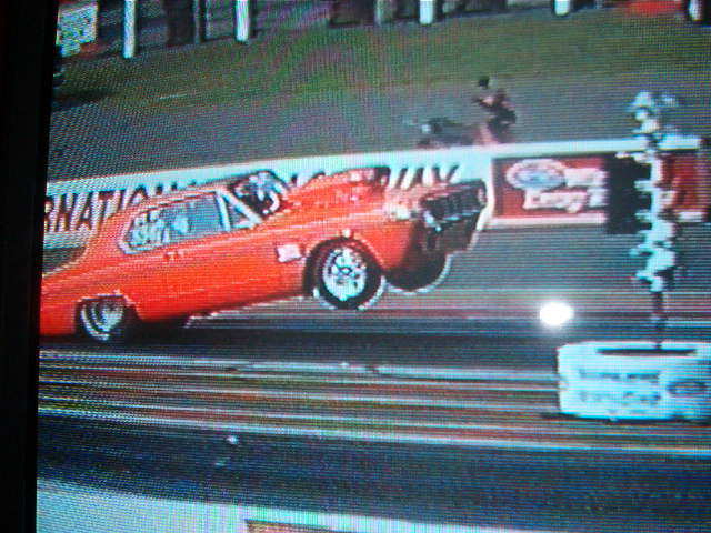
67 RO23 clone with 6.1 SRT Hemi and dual quads. Soon to have Drag Pak induction and Throttle body.
|
|
|
Re: Main Bearings question
[Re: ntstlgl1970]
#1370130
02/28/15 05:50 PM
02/28/15 05:50 PM
|
Joined: Nov 2009
Posts: 3,410
Belpre,Ohio
CHAPPER
master
|
master
Joined: Nov 2009
Posts: 3,410
Belpre,Ohio
|
I used ACL bearings with the Molnar crank and rods. 1100+ 3/8 mile laps and all look new. I have been using the stock thrust bearing and amazed at how well it holds up.
If you like drag racing, support your local track.
|
|
|
|
|


