Moparts
572 B1 org Part 5 - Build Notes
Posted By: 440Jim
572 B1 org Part 5 - Build Notes - 09/24/21 02:05 AM
This topic is 572 B1 org Part 5 - Build Notes
Here is my plan for posting progress:
572 B1 org Part 1-Buying Parts
572 B1 org Part 2-Component Observations
572 B1 org Part 3-Machine Shop Report
572 B1 org Part 4-Mock-ups
572 B1 org Part 5-Build Notes
572 B1 org Part 6-Dyno Results
572 B1 org Part 7-Track Testing
Engine Summary:
572 CID (4.500” bore x 4.500” stroke) 14.3 CR Approximately 14.7 CR (final CR will be after measuring piston to deck during assembly)
B1 original Heads, CNC Ported 429/326 cfm at 0.800” lift, milled to 60cc chambers, 332cc intake ports, 125cc exhaust ports
T&D paired rocker arms 1.7 ratio, part number 8013, 5/8” shafts
B1 cast single 4-barrel intake manifold with RB spacers.
ICON Elite forged Pistons # IC433CAKTS.std with rings & 0.185” wall Trend wrist pins, 1.355 Compression height, -6.5cc net relief, lateral gas ported
Rings 0.043" top SS with CrN, 1/16" Napier 2nd, 3/16" oil ring
Cometic 5-layer MLS head gaskets 4.530” dia x 0.056” thick
Cam duration 282/295 at 0.050”, 0.800” lift, 113 LSA
7/16 dia Comp Cams 8649 pushrods, 9.800” long, 0.165” wall, ball-ball ends, pushrod oiling
2-1/4” primary headers with 4” collectors
Posted By: 440Jim
Re: 572 B1 org Part 5 - Build Notes - 09/24/21 02:05 AM
Part 5 – Bearing Clearances. Build Notes
0.0028” to 0.0029” Main Bearings Clevite MS1277HG full groove
0.0026” to 0.0027” Rod Bearings Clevite CB743 (half HN, half HXN)
I used one bearing shell from the HN bearings and one shell from the HXN bearings to get this clearance.
Posted By: 440Jim
Re: 572 B1 org Part 5 - Build Notes - 09/24/21 02:17 AM
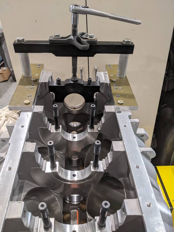
Part 5 – Main Cap Install (tool). Build NotesI use this main cap install tool to press the caps straight down. I made this when I had the KB aluminum block.
It makes installing main caps with the side bolts easy. And since I don't have to tap the caps with a hammer, the bearing shells stay in place during installation.

The plates that bolt to the oil pan rail have a series of holes to align each cap position with the press.
Posted By: 440Jim
Re: 572 B1 org Part 5 - Build Notes - 09/24/21 02:22 AM
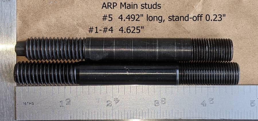
Part 5 – Main Studs, BMP Block. Build NotesThe BMP block comes with ARP main studs. These are the dimensions.
Posted By: Moparteacher
Re: 572 B1 org Part 5 - Build Notes - 09/24/21 04:14 AM
Part 5 – Main Cap Install (tool). Build NotesI use this main cap install tool to press the caps straight down. I made this when I had the KB aluminum block.
It makes installing main caps with the side bolts easy. And since I don't have to tap the caps with a hammer, the bearing shells stay in place during installation.

The plates that bolt to the oil pan rail have a series of holes to align each cap position with the press.
That's pretty slick. Thanks for sharing.
Posted By: Cab_Burge
Re: 572 B1 org Part 5 - Build Notes - 09/24/21 06:04 AM
I've use a plastic and rubber tip hammer

I would have never thought of doing what your doing, yours is Good


Posted By: 440Jim
Re: 572 B1 org Part 5 - Build Notes - 09/24/21 11:58 AM
Sometimes with tight fitting side bolted caps, the bearing shell will fall out when tapping the cap down with a mallet, etc.
I have seen some people use a zip tie to hold the bearing shell, until just before the cap reaches the crankshaft, then remove the zip tie and tap all the way down.
This fixture uses little force since it presses straight and even (centered).
Posted By: n20mstr
Re: 572 B1 org Part 5 - Build Notes - 09/24/21 01:49 PM
Jim i use the exact same thing to press the caps on. Also use a threaded rod with a washer and nut to pull the cap out. One thing i do you may want to do, use a scrap piece of 1/2 or thick alum between the cap and the press. Saves the cap from getting any scratches/marks on it. Not sure if it really matters but that what i have been doing
Posted By: moparx
Re: 572 B1 org Part 5 - Build Notes - 09/24/21 04:23 PM
Part 5 – Main Cap Install (tool). Build NotesI use this main cap install tool to press the caps straight down. I made this when I had the KB aluminum block.
It makes installing main caps with the side bolts easy. And since I don't have to tap the caps with a hammer, the bearing shells stay in place during installation.

The plates that bolt to the oil pan rail have a series of holes to align each cap position with the press.
That's pretty slick. Thanks for sharing.
i say so as well !


Posted By: 440Jim
Re: 572 B1 org Part 5 - Build Notes - 09/24/21 04:33 PM
Jim i use the exact same thing to press the caps on. Also use a threaded rod with a washer and nut to pull the cap out. One thing i do you may want to do, use a scrap piece of 1/2 or thick alum between the cap and the press. Saves the cap from getting any scratches/marks on it. Not sure if it really matters but that what i have been doing
I use the long threaded rod to pull them also. I actually used a 3/8 threaded rod that I turned down the end on the lathe to 5/16" and rethreaded it to fit the caps. Overkill, yes...
A slide hammer does work fine for removal, but since I have the main cap "bridge" it is nicer to smoothly pull the cap off.
Posted By: 440Jim
Re: 572 B1 org Part 5 - Build Notes - 10/21/21 08:06 PM
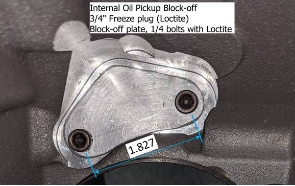
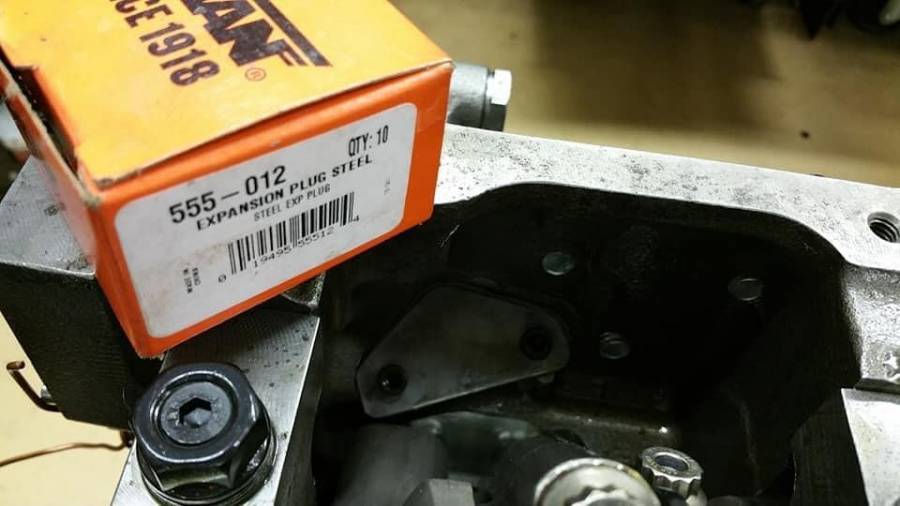
Part 5 – Internal oil pickup block-off. Build NotesI am using the Milodon external oil pickup lines through the oil pan, so the internal oil pickup hole needs to be blocked-off.
I used a ¾” freeze plug in the BMP block hole (with Loctite), and for good measure also made a retention plate so the freeze plug could never fall into the engine. The retention plate replaces the ½ NPT adaptor that comes with the BMP block. Loctite the ¼ allen head bolts and torque to 100 lb-in.
Posted By: 440Jim
Re: 572 B1 org Part 5 - Build Notes - 10/21/21 08:07 PM
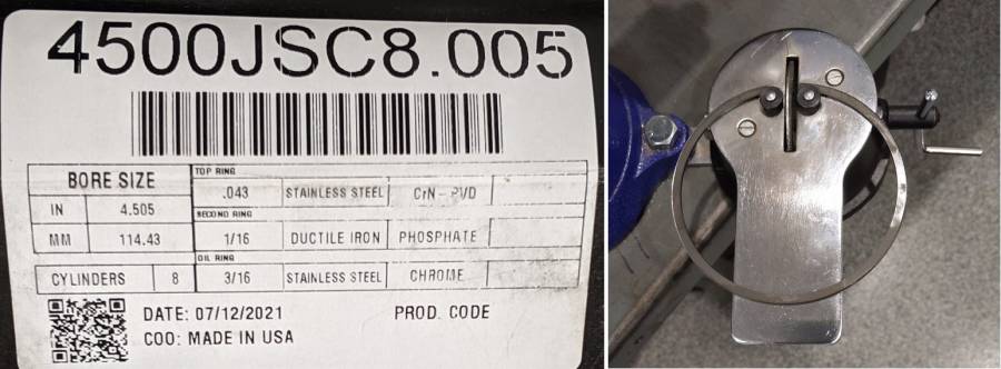
Part 5 – Piston Ring end gap. Build NotesI finished file fitting my rings to set the end gap.
0.022” Top ring 0.043” (Gas ported piston)
0.025” 2nd ring 1/16” Napier
Posted By: ZIPPY
Re: 572 B1 org Part 5 - Build Notes - 10/21/21 08:57 PM
Part 5 – Internal oil pickup block-off. Build Notes
I am using the Milodon external oil pickup lines through the oil pan, so the internal oil pickup hole needs to be blocked-off.
I used a ¾” freeze plug in the BMP block hole (with Loctite), and for good measure also made a retention plate so the freeze plug could never fall into the engine. The retention plate replaces the ½ NPT adaptor that comes with the BMP block. Loctite the ¼ allen head bolts and torque to 100 lb-in.
Nice detail!
Did similar on the "Pre-Callies" MP/World/FCA iron.
Pic added for a handy part number.
Posted By: 440Jim
Re: 572 B1 org Part 5 - Build Notes - 10/22/21 01:24 AM
Yes, that is the freeze plug (expansion plug) I used.
Dorman 555-012 Steel Cup Expansion Plug 3/4 In.,
Height: 0.250
Closed End Diameter: 0.747 in
Open End Diameter: 0.760 in
Describe Type: Cup Type
Material: Steel
Posted By: 440Jim
Re: 572 B1 org Part 5 - Build Notes - 10/27/21 01:11 AM
I am trying to put some time into assembling this motor....
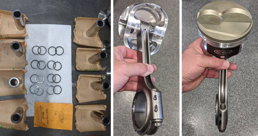
Today I assembled the pistons to the rods. I am careful, and painfully slow; but progress!
The first Spirolox took about the same amount of time as doing the last 4 pistons combined.
I don't build new motors too often... And my fingers are not small.
Posted By: tboomer
Re: 572 B1 org Part 5 - Build Notes - 10/27/21 11:15 AM
Looks good Jim!

Posted By: 440Jim
Re: 572 B1 org Part 5 - Build Notes - 11/01/21 01:02 PM
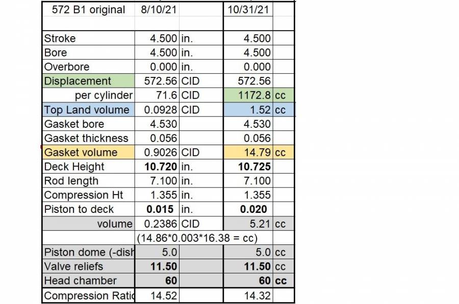
Part 5 – Compression Ratio. Build NotesAfter putting the pistons/rods in the block, I was able to measure the actual piston to deck height. The machine shop decked the block to remove the minimum needed to make sure it was square and even with the desired surface finish. They didn’t report a final deck height, so the actual piston to deck was used to calculate the deck height of 10.725”. The rod lengths were measured and were spot on the spec 7.100” length. The pistons are 0.020” down the hole. I was expecting about 0.015” since I thought the final deck height was going to be shorter. I am using custom sized Cometic 5-layer MLS head gaskets with a 4.530” bore and 0.056” thickness. This makes the final Compression Ratio 14.3
Posted By: 440Jim
Re: 572 B1 org Part 5 - Build Notes - 11/01/21 01:04 PM
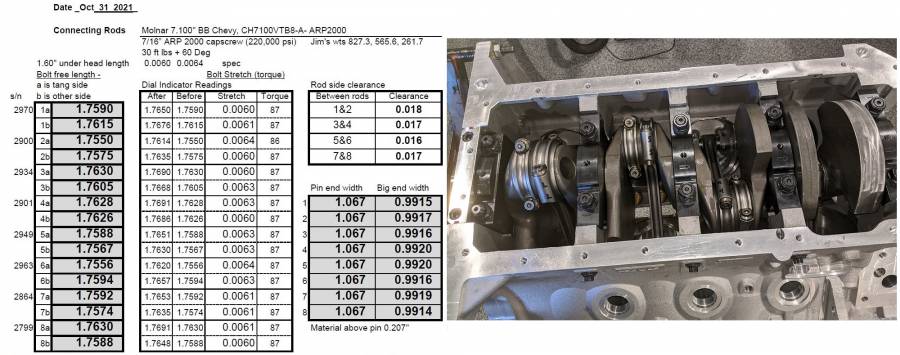
Part 5 – Blue Print Measurements. Build NotesI like to document or “Blue Print” my race engines. The crank endplay was 0.005” with the new main bearings (MS1277HG). The torque required to turn the engine was 30 ft-lbs. This is mostly from the rings. Both the ring widths and the oil ring tension affects this. Here is one sheet I made from assembly measurements.

Posted By: HardcoreB
Re: 572 B1 org Part 5 - Build Notes - 11/02/21 01:12 PM
Did you 'drag-check' the oil rings with a fish scale? I know some that have gotten away from the practice of adjusting and reducing tension on the oil rings. On my 3/16 oil rings, i was able to set the drag about 11lbs. But i have a drysump which puts a vacuum on the crankcase.
Posted By: 440Jim
Re: 572 B1 org Part 5 - Build Notes - 11/02/21 03:09 PM
Did you 'drag-check' the oil rings with a fish scale?
No I did not. I probably should have done that before putting the crank in the block. I have done that before.
That is the only way to be sure how much drag is from the oil rings. Some is from the tacky assembly lube in the bearings too.
My previous 4.500" bore motor (in 2014) needed 25 ft-lbs to turn everything. 0.043/0.043/(3/16) Total Seal rings that are marketed as standard tension. But "standard" could be 18 lbs tension or 22 lbs etc.; I have seen some specs for low tension very from 11 to 16 lbs.
Posted By: Cab_Burge
Re: 572 B1 org Part 5 - Build Notes - 11/02/21 05:03 PM
Is that 30 Lbs. the break away or rotational torque?
I do NOT use any assembly lube on any bearing surfaces

,
The motor runs on oil so that is what I use to assemble them, I do pre oil them using a drill motor spinning the oil pump and then spin them over on the starter with the plugs out


Posted By: 440Jim
Re: 572 B1 org Part 5 - Build Notes - 11/02/21 05:19 PM
Is that 30 Lbs. the break away or rotational torque?
That is turning it as close to a constant rate as I can using a beam style torque wrench.
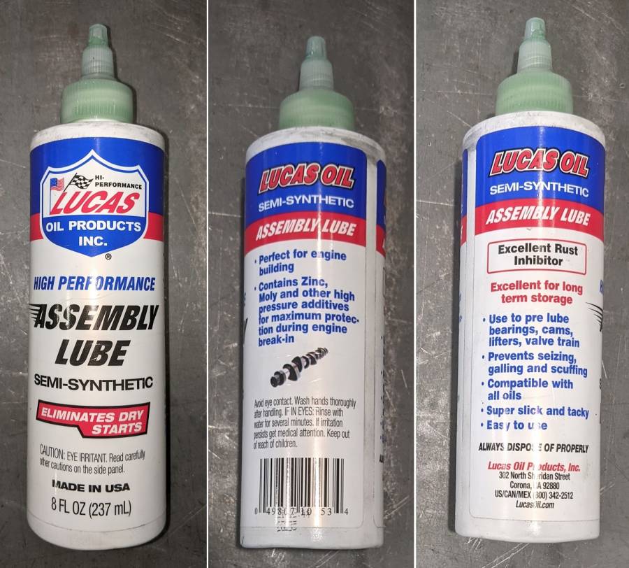
I always use a tacky assembly lube designed for bearings. You never know how long the engine will sit (until spring?) before you start it.
Posted By: 440Jim
Re: 572 B1 org Part 5 - Build Notes - 11/16/21 06:23 PM
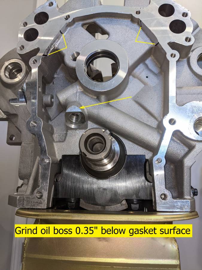
Part 5 – Jesel Belt Drive. Build NotesI decided to use a Jesel cam belt drive instead of the Australian unit. I didn't like the interference with the ATI SuperDamper.
My block did need a little more clearance work to fit the Jesel baseplate. Between the bolt holes at 45 degrees to the top.
Posted By: JERICOGTX
Re: 572 B1 org Part 5 - Build Notes - 11/16/21 08:57 PM
I decided to use a Jesel cam belt drive instead of the Australian unit. I didn't like the interference with the ATI SuperDamper.
My block did need a little more clearance work to fit the Jesel baseplate. Between the bolt holes at 45 degrees to the top.
Just looked at pictures of my INDY block, and it doesn't have the oil boss, and it looked like it was clearanced at the top of the cover like yours just a bit.
Good write up Jim.
Posted By: 440Jim
Re: 572 B1 org Part 5 - Build Notes - 11/17/21 01:52 AM
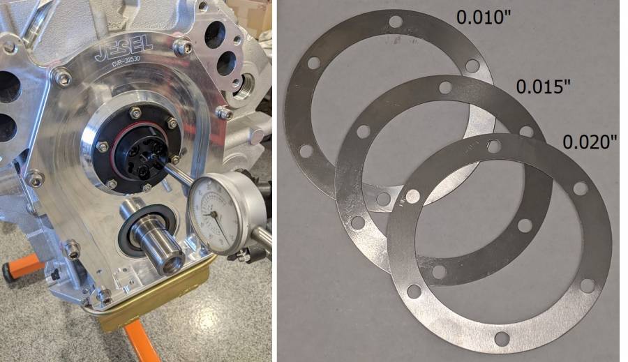
Jesel provides steel shims with 6 bolt holes to go under their thrust plate/seal in this picture. They are used to set cam end play. Done.
Posted By: scottb
Re: 572 B1 org Part 5 - Build Notes - 11/17/21 02:40 AM
Looks very nice
Posted By: 440Jim
Re: 572 B1 org Part 5 - Build Notes - 11/18/21 01:40 PM
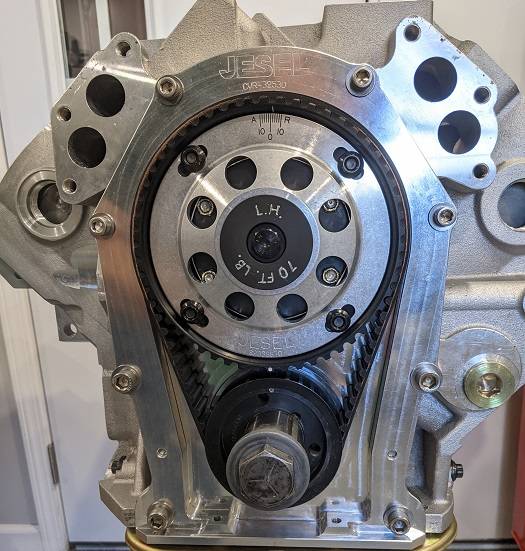
Jesel installation complete.
I did one cam degree check after installation and it was good.
Today I will "map" the cam at several installed positions (+2, 0, -2) for lobe lift near TDC. I use that to know how piston to valve clearance will change if I change cam degree later.
Posted By: HardcoreB
Re: 572 B1 org Part 5 - Build Notes - 11/18/21 01:48 PM
Jesel installation complete.
I did one cam degree check after installation and it was good.
Today I will "map" the cam at several installed positions (+2, 0, -2) for lobe lift near TDC. I use that to know how piston to valve clearance will change if I change cam degree later.
Hey Jim! I'm assuming this pic has the ICL about where you want it to be? If so, Jesel hasn't changed the indexing on the cam pulley. Every Jesel I have seen true "0" shows-up retarding, if that makes sense!?
Posted By: 440Jim
Re: 572 B1 org Part 5 - Build Notes - 11/18/21 06:13 PM
Hey Jim! I'm assuming this pic has the ICL about where you want it to be? If so, Jesel hasn't changed the indexing on the cam pulley. Every Jesel I have seen true "0" shows-up retarding, if that makes sense!?
No, that was the starting point for today's ton of measurements. Two degrees retarded is the last place I expect to leave it, so I start there and change it for all my measurements.
Part 5 – Cam Mapping. Build NotesThis morning I completed mapping the cam lobe events at three positions. Every mark on the Jesel did result in 2 crankshaft degrees change in timing (within measurement tolerance).
The cam card recommends 111 deg intake, 115 deg exhaust (113 LSA). I call that 2 degrees actual advance. When I set the Jesel marks to +2 advanced, this is what I measured.
It might be more information than most people want... Many should just look at the measurements at 0.050" lobe lift.
The way I look at it and the way this cam is ground, to get the intake lobe centerline at 113 ATC ("true zero"), the Jesel would be set at 1/4 deg retarded.
When I did these measurements with the Jesel at the zero mark, I came up with the intake lobe centerline 112.75 ATC (at 0.050" tappet lift).
I might set it at +4 this afternoon, just for more piston to valve information. But I don't plan to run it there based on these measurements.

Posted By: 440Jim
Re: 572 B1 org Part 5 - Build Notes - 11/18/21 07:11 PM
For What Its Worth (FWIW),
With the cam's 113 LSA, I expect to run the intake lobe timing between 109 and 113 ATC.
I call that +4 degrees advanced to +0 (no advance).
Posted By: dart9ss
Re: 572 B1 org Part 5 - Build Notes - 11/19/21 02:08 AM
some great info here should dyno big numbers!

Posted By: 440Jim
Re: 572 B1 org Part 5 - Build Notes - 11/19/21 10:01 PM
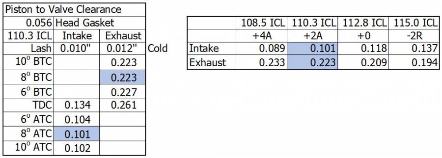
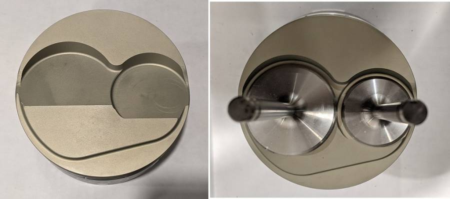
Part 5 – Piston to Valve Clearance. Build NotesHere is the piston to valve clearance I measured.
The ICON piston specs are:
Intake Valve Depth/Dia: 0.320 / 2.526
Exhaust Valve Depth/Dia: 0.325 / 1.980
Posted By: Cab_Burge
Re: 572 B1 org Part 5 - Build Notes - 11/19/21 10:17 PM
That baby has a hoop of V to P clearances


Posted By: 440Jim
Re: 572 B1 org Part 5 - Build Notes - 11/20/21 12:38 AM
IMO, these are big valve reliefs.
Needed for 0.800" lift and lots of duration.
Worked out fine.
Posted By: AndyF
Re: 572 B1 org Part 5 - Build Notes - 11/20/21 05:59 AM
Did you measure valve drop at TDC? I always keep track of valve drop since it gives a baseline to work against if I decide to change cams. Also, on you PV measurements are you using checking springs or the real springs? Real springs add some clearance since everything bends away from the piston.
Posted By: 440Jim
Re: 572 B1 org Part 5 - Build Notes - 11/20/21 01:12 PM
Did you measure valve drop at TDC? I always keep track of valve drop since it gives a baseline to work against if I decide to change cams. Also, on you PV measurements are you using checking springs or the real springs? Real springs add some clearance since everything bends away from the piston.
I have never tried to push the valve down to the piston with real racing valve springs installed. As far as valve drop, I measure the cam lobe lift at TDC (and other positions) and the piston to valve clearance at TDC (and other positions); so I have the information you need to compare to other cams. See the tables I have posted.
It is nice when some cam vendors publish the lobe lift at TDC. Even though it only applies to a certain installed lobe centerline.
Posted By: gregsdart
Re: 572 B1 org Part 5 - Build Notes - 11/21/21 12:43 AM
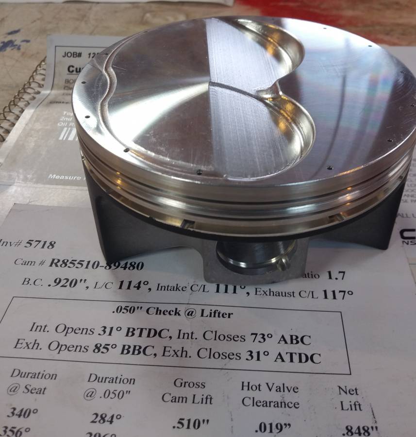
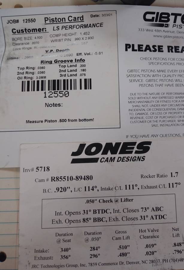
These new Pistons were cut using a piston from the old short block, same cam , same 440/1 heads cut to 62cc.
Had . 104 intake clearance at 110 cl. .140 ex at same installed centerline.
Posted By: 440Jim
Re: 572 B1 org Part 5 - Build Notes - 11/21/21 12:38 PM
Had . 104 intake clearance at 110 cl. .140 ex at same installed centerline.
That worked out nicely.

Posted By: WadeMetzinger
Re: 572 B1 org Part 5 - Build Notes - 11/22/21 02:03 PM
Very interesting and informative, thanks for sharing Jim. I wouldn't have a clue how to take/do all those measurements you did.
I degree the cam to ensure it's installed where I want it. Then I check P-to-V, find the tightest spot and when using belt system, I'll check the P-to-V at +/- 4 degrees from that tightest spot incase we want to try different locations (although I've never move one after dyno and installed).
Posted By: 440Jim
Re: 572 B1 org Part 5 - Build Notes - 11/26/21 06:10 PM
I hope to have progress to report tonight. Getting some work done. These roller springs are stiff compared to solid lifters... LOL
Lunch break right now.
I need to buy a new crank bolt, this is an old long one from the scavenger pile.
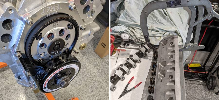
The good news from yesterday, the timing mark aligned perfectly at TDC check with the pointer & Super Damper. I like to verify that before I put the heads on. Easier with the dial indicator on the piston. I check timing marks at 0.050" before TDC and 0.050" after TDC... Top is halfway between. Typically around ~11 degrees each side.
Posted By: Harry's Taxi 2
Re: 572 B1 org Part 5 - Build Notes - 11/26/21 06:45 PM
I'd suggest verifying cam specs.
Posted By: 440Jim
Re: 572 B1 org Part 5 - Build Notes - 11/27/21 02:08 AM
I'd suggest verifying cam specs.
Did you miss this post on Nov 18th?
[url=https://board.moparts.org/ubbthreads/ubbthreads.php/topics/2986438/re-572-b1-org-part-5-build-notes.html#Post2986438][/url]
Posted By: 440Jim
Re: 572 B1 org Part 5 - Build Notes - 11/27/21 02:15 AM
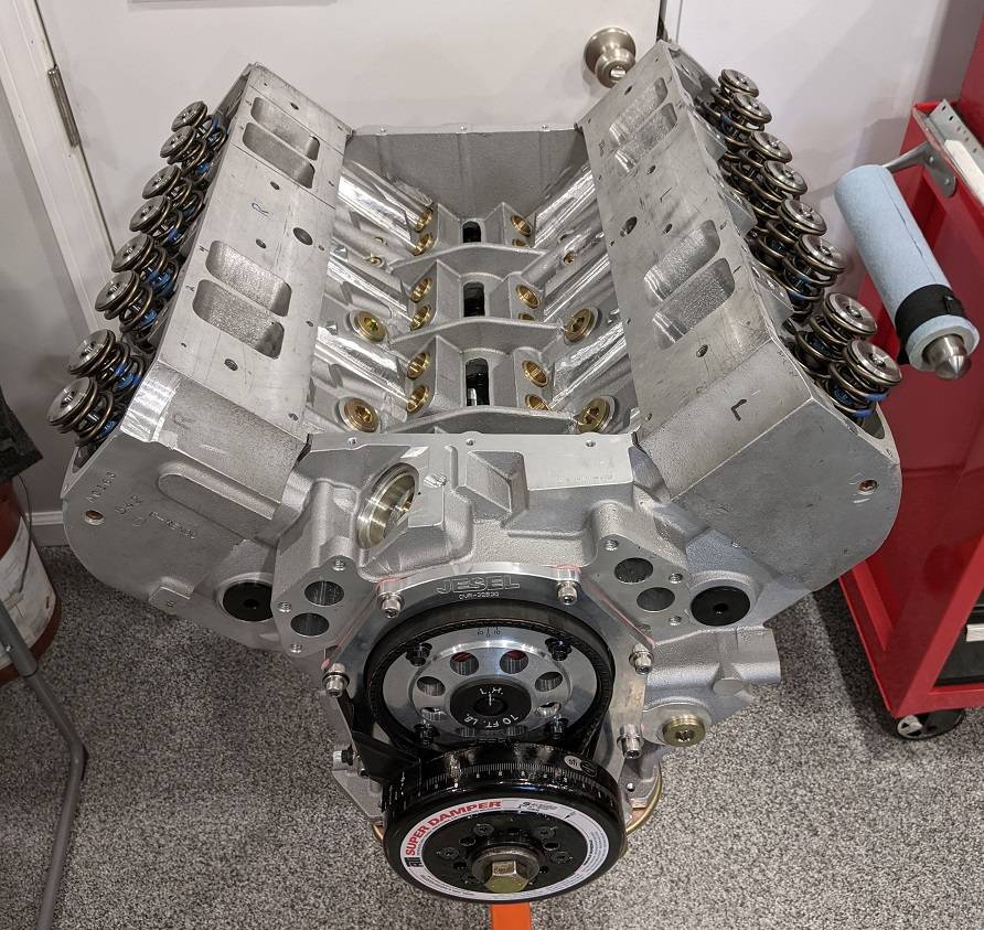
I was hoping to have the heads torqued today, but it didn't happen.
I have the heads on the studs, with head gasket, etc. But tomorrow will have to be the day to lube and torque all the head stud nuts.
I was happy to finish the setup of the heads with proper valve spring heights, seals, etc. Lots of little details seem to take me a lot of time. But that makes me happy.

I did buy a new crank/damper bolt, some 10-32 set screws , and new spark plugs on my way home from lunch today.
The set screws go in the head holes that can be used to restrict rocker oiling from the block to the rockers/heads. They are under the rocker stands. So if somebody wanted to remove the paired T&D rockers and put the long single shaft rockers on these heads (which oil from the block), they would not have to pull the heads, just the rockers and replace these solid set screws.
But I am using pushrod oiling... hence the solid set screws (instead of drilled restrictors.) These are in the heads, not the block (which can be restricted/plugged also, since the block is threaded.)
Posted By: 440Jim
Re: 572 B1 org Part 5 - Build Notes - 11/27/21 03:00 AM
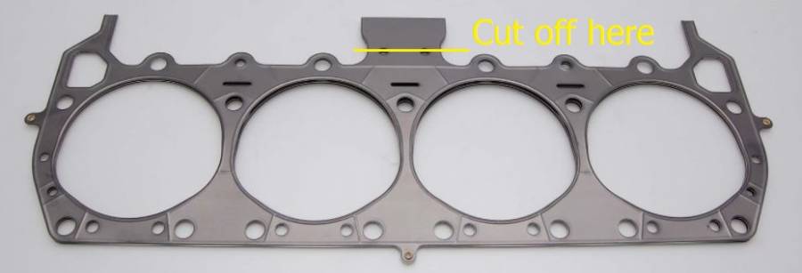
This is one of the little details I had to do today.
Cut off the useless "tab" on the Cometic head gaskets. Which can interfere with pushrods on some applications.
Posted By: Cab_Burge
Re: 572 B1 org Part 5 - Build Notes - 11/27/21 07:12 AM
Posted By: Harry's Taxi 2
Re: 572 B1 org Part 5 - Build Notes - 11/27/21 11:32 AM
I'd suggest verifying cam specs.
Did you miss this post on Nov 18th?
[url=https://board.moparts.org/ubbthreads/ubbthreads.php/topics/2986438/re-572-b1-org-part-5-build-notes.html#Post2986438][/url]
Apparently i did.....sorry to say that i don't follow your every post. i have bought 4 cams lately that have been from 2-6 degrees off on intake lobes and 2 of those are from the same grinder you used.
You're welcome for the reminder just the same.
Posted By: 440Jim
Re: 572 B1 org Part 5 - Build Notes - 11/27/21 02:40 PM
i have bought 4 cams lately that have been from 2-6 degrees off on intake lobes and 2 of those are from the same grinder you used.
You're welcome for the reminder just the same.
Thanks for letting me know of your experience. I bought this cam from another racer that never used it. It came in a package deal with my B1 heads, intake, valve covers, valley plate, etc.
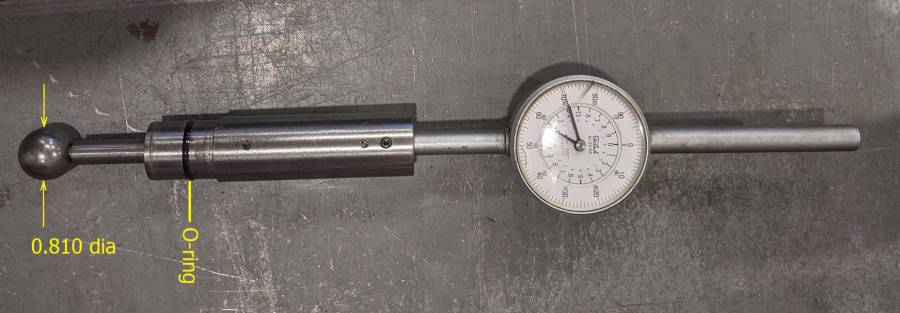
I measured the lobes using a dial indicator type follower with 0.810" dia. My roller lifters (Comp 892 offset seats, pushrod oiling) have 0.800" dia wheels. If the dia is significantly different, it can change lobe numbers slightly.
Both intake and exhaust measured 1-2 degrees more than the cam card. I actually measured 5 intake and exhaust lobes (different cylinders).
Posted By: 440Jim
Re: 572 B1 org Part 5 - Build Notes - 11/28/21 09:20 PM
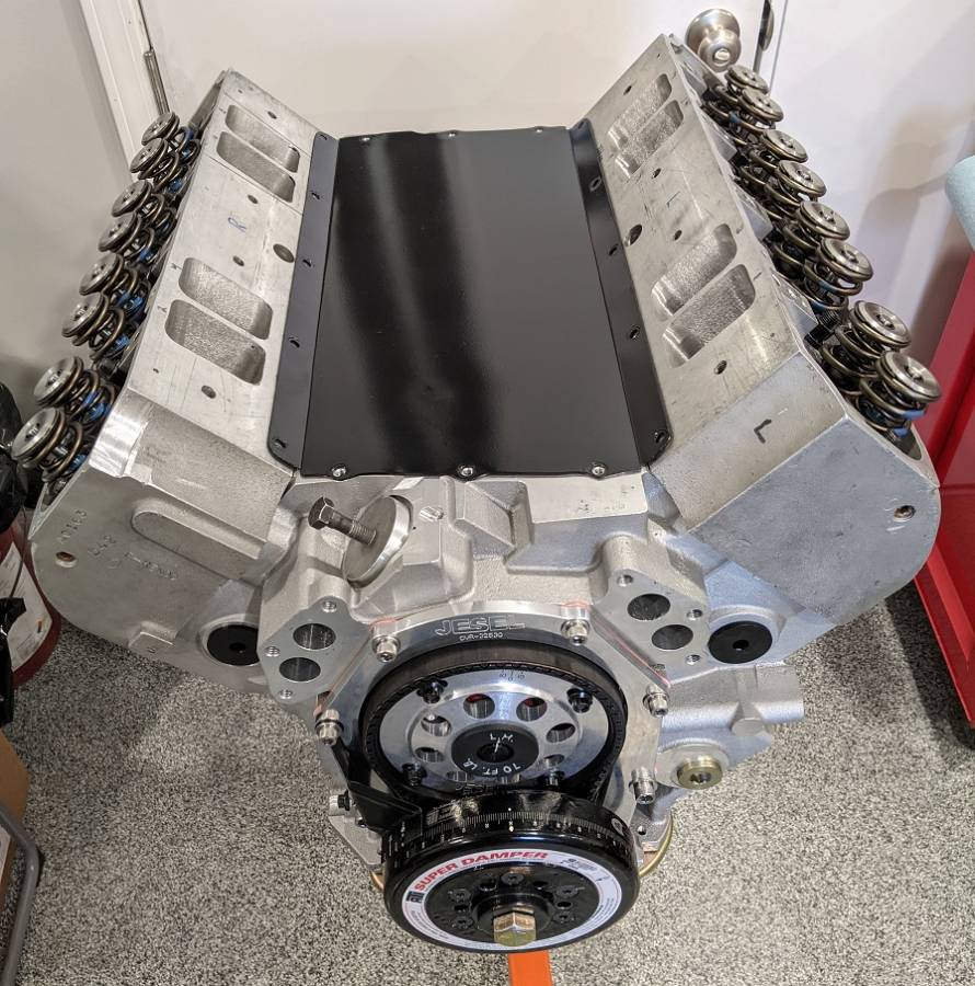
One build note when torqueing the heads.
Those 1.63" dia springs don't leave much room to torque the heads. Especially the very center stud/nut between two springs
I used my 3/8 drive socket with a 3/8 to 1/2 adapter to my torque wrench. My 1/2 drive socket didn't fit between them.
Posted By: Al_Alguire
Re: 572 B1 org Part 5 - Build Notes - 11/29/21 05:07 PM
We turn down a socket to get to the center head stud nuts. Yep the tab is defintely useless, and the placement of the damn rivets

Posted By: 440Jim
Re: 572 B1 org Part 5 - Build Notes - 12/05/21 04:19 PM
Part 5 – Intake Gaskets. Build NotesThis note may be fairly specific to the porting on my heads/intake, but the gasket info may be of interest to other B1 head users.
I had previously bought gaskets from Koffel's Place, and those are 1.60 x 2.66. Those are smaller than the ports on my heads.
I bought these intake manifold gaskets from FlatOut Gaskets and they fit my head ports very well. They are part number 8185 and their catalog lists the size as 1.75 x 2.82
FlatOut makes lots of different gaskets, this link is to the various thicknesses of the #8185
FlatOut Gaskets 8185The gaskets have two corners clipped, and they fit my heads with those corners on the bottom! This way, the top of the gasket aligns well with the valve cover sealing surface.
And just like the Koffel's gaskets, I need to trim the area under the bolt holes for the B1 valley plate.

Posted By: moparx
Re: 572 B1 org Part 5 - Build Notes - 12/05/21 05:22 PM
nice gaskets and pretty reasonable pricing as well.


Posted By: 440Jim
Re: 572 B1 org Part 5 - Build Notes - 12/05/21 07:00 PM
I like the FlatOut gaskets. And several choices even a steel core.
FWIW, this pic shows the port misalignment if I put the cropped corners UP. The gasket hole centerline is 0.030" different than the port centerline.
So flipping the gasket moves the port opening 0.060"

Posted By: AndyF
Re: 572 B1 org Part 5 - Build Notes - 12/05/21 07:32 PM
You should send those pictures to the mfg and see what they say. They might have their drawing wrong or they might not know. The aftermarket is full of parts that are built wrong because somebody made an error and nobody ever pointed it out.
Posted By: 440Jim
Re: 572 B1 org Part 5 - Build Notes - 12/05/21 08:04 PM
You should send those pictures to the mfg and see what they say. They might have their drawing wrong or they might not know. The aftermarket is full of parts that are built wrong because somebody made an error and nobody ever pointed it out.
I will do that. But the shop that ported my heads (before I bought them) may have moved the ports too. But I just thought the gasket hole centerline would be the same as the gasket port centerline.
Posted By: AndyF
Re: 572 B1 org Part 5 - Build Notes - 12/05/21 10:31 PM
Does the gasket line up with the ports in the intake? If all three parts line up together then you have a winner. I don't know what the cut corners are for. Maybe they are supposed to go down but that does seem odd.
Posted By: fast68plymouth
Re: 572 B1 org Part 5 - Build Notes - 12/05/21 11:11 PM
I built a 572 several years ago using 572-13 heads and a Bill Mitchell/Mopar aluminum block.
The heads used Jesel rockers and I thought I’d be clever and pushrod oil with the 892 lifters.
As it turned out, the Chevy oriented oil holes in the lifters lined up perfectly with the oil feed hole in the lifter bushing with the .484 lobe lift cam with it on the base circle.
When I went to prime the oil system, as soon as the drill started to lug down from the load of pumping the oil....... oil shot out of the top of a few of the adjuster screws about 20ft across the shop.
The correct oil hole orientation in the lifter for a Mopar is to have them parallel to the axle...... not perpendicular.
For proper oil “metering” to the top end with edge orifice oiling type lifters, the pressurized oil in the oil band squeezes between the lifter bore and the lifter body to get into the pushrod feed hole above the band.
In my situation, with the oil hole in the lifter bore/lifter body lined right up with each other, I had totally unrestricted oil to the top end whenever the lifter was close to being on the cams base circle.
Which wouldn’t have been good at all.
So, I took the path of least resistance........ 87019 lifters(892’s with no oil hole) and spray bar valve covers.
Jim, If you haven’t verified this isn’t a problem on your build, I wouldn’t wait until the last thing to check it.
On my build, even running the drill very slow resulted in oil just gushing out of any rocker that was nearly closed.
Posted By: 440Jim
Re: 572 B1 org Part 5 - Build Notes - 12/06/21 02:02 AM
Does the gasket line up with the ports in the intake? If all three parts line up together then you have a winner. I don't know what the cut corners are for. Maybe they are supposed to go down but that does seem odd.
Andy,
The intake runners are tapered toward the heads. So at the intake manifold, the ports are smaller then the large CNC ported heads. Although the previous owner did open up the intake manifold some, the rest of the transition occurs in the ~0.75" thick RB intake manifold spacers. My intake manifold exit is actually larger than the Koffel's gaskets, but not as big as the heads. Remember, the B1 intake fits a low deck block and the RB spacers are used for a RB block.
Fast68plymouth,
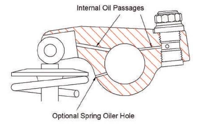
I have done lots of measurements on the BMP block lifter bore bushing 0.035" oil hole, the cam base circle, and the Comp 892 lifter oil hole. That is an entire topic on its own.
Thanks for the heads-up. Just like my KB motor, I will prime the system after it is all together to see what the rocker oiling looks like. Fingers crossed.
I have T&D rockers, rather than Jesel. FWIW
The cam I have for this engine has a slightly different base circle diameter, than the one on my buddies 440-SR headed engine with BMP aluminum block. But he used Indy oil lines, not pushrod.
I used the same Comp lifters on my last 440-1 heads and KB aluminum block engine and the head oiling was perfect. But there are lots of differences....
The valve covers that came with my heads have spray bars if that is needed. But if the lifters/pushrods put too much oil to the heads, it will require changes. Ugh!
Posted By: AndyF
Re: 572 B1 org Part 5 - Build Notes - 12/06/21 02:19 AM
I had an oiling issue when using Crower roller lifters but I never had any issue using the Comp AMC lifters. It is something to always double check though. All depends how the lifter is getting the oil.
Posted By: fast68plymouth
Re: 572 B1 org Part 5 - Build Notes - 12/06/21 02:22 PM
The Comp AMC lifters have the pushrod oil feed hole in the correct position for a Mopar....... parallel with the axle.
Posted By: 440Jim
Re: 572 B1 org Part 5 - Build Notes - 12/13/21 09:01 PM
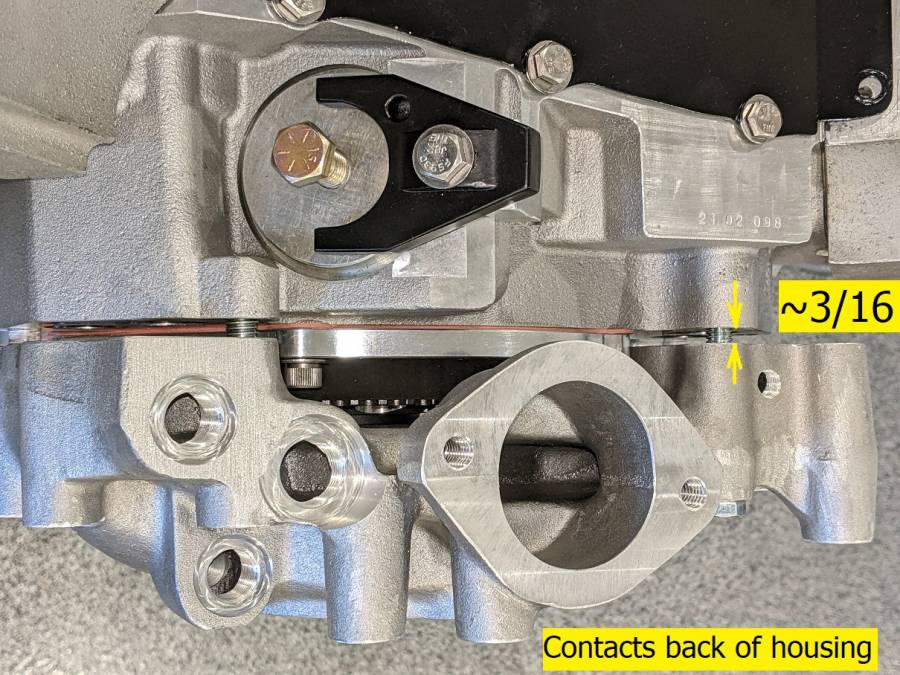
Part 5 – Water Pump Housing to Jesel Belt Drive. Build NotesA typical water pump housing will not clear the Jesel Belt Drive. The housing contacts the center of the cam pulley (adapter/nut area) leaving a gap about 3/16” between the block and the housing. Since I am using a 1/4” thick front engine plate (and a midplate between engine & trans), everything will clear.
Posted By: AndyF
Re: 572 B1 org Part 5 - Build Notes - 12/13/21 10:07 PM
Yeah, a motor plate plus a couple of gaskets should get that to clear. I always use a 3/8 motor plate and those clear. If you use a belt driven distributor then you have space the water pump housing out about an inch.
Posted By: HardcoreB
Re: 572 B1 org Part 5 - Build Notes - 12/14/21 01:32 PM
For me Jim, I'd probably go to a remote pump mounted on the lower rad tank or thereabouts. It gets things out of the way and shifts some weight lower and towards the pass side. It's pretty easy to fab up some threaded pucks to route water in/out. you could even get fancy and reverse flow it at no addl. upcharge.
Posted By: 440Jim
Re: 572 B1 org Part 5 - Build Notes - 12/28/21 02:50 PM
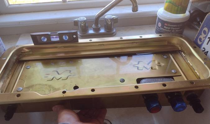
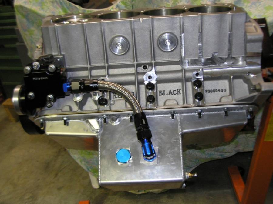
Part 5 – Oil Pan & Oil Level. Build NotesAfter installing the fittings for the external oil pump pickup and the B1 head drain lines, I capped the connections and did a water leak test. While doing this, I measured the water added to see where the oil level would be with 7 and 8 qts. The MIL-31150 pan has a built in windage tray that mounts to the metal bridges at the front/center/rear of the oil pan. With 7 qts the level was below these bridges. With 8 qts it was slightly above these bridges; less than 1/8" front. The built-in windage tray slants toward the rear, similar (but less) to the bottom of the pan (4” sump front, 5” sump rear).


Posted By: A727Tflite
Re: 572 B1 org Part 5 - Build Notes - 12/28/21 03:45 PM
Part 5 – Oil Pan & Oil Level. Build Notes
After installing the fittings for the external oil pump pickup and the B1 head drain lines, I capped the connections and did a water leak test. While doing this, I measured the water added to see where the oil level would be with 7 and 8 qts. The MIL-31150 pan has a built in windage tray that mounts to the metal bridges at the front/center/rear of the oil pan. With 7 qts the level was below these bridges. With 8 qts it was slightly above these bridges; less than 1/8" front. The built-in windage tray slants toward the rear, similar (but less) to the bottom of the pan (4” sump front, 5” sump rear).
Where is the water level when the pan is at a 45 ?
Posted By: 440Jim
Re: 572 B1 org Part 5 - Build Notes - 12/28/21 04:26 PM
Where is the water level when the pan is at a 45 ?
I have not tried that. When I empty it after 24hrs, I will
estimate when it starts to overflow the rear rail.
One nice thing about the Milodon pans in this series; the built-in windage tray actually traps the oil beneath it. So it slows the transient movement out of the sump under extreme circumstances.
Posted By: A727Tflite
Re: 572 B1 org Part 5 - Build Notes - 12/28/21 08:19 PM
Where is the water level when the pan is at a 45 ?
I have not tried that. When I empty it after 24hrs, I will
estimate when it starts to overflow the rear rail.
One nice thing about the Milodon pans in this series; the built-in windage tray actually traps the oil beneath it. So it slows the transient movement out of the sump under extreme circumstances.
Good to know.
Posted By: gregsdart
Re: 572 B1 org Part 5 - Build Notes - 12/28/21 11:14 PM
Jim, are you forced into that shallow pan by your chassis? Many years ago I read where an SS hemi kept eight quarts of oil wrapped around the crank at eight thou rpm. Seems I have always been in a fight to keep the pickup covered. I currently run a 3 qt accusump and total 12 qts in a much larger pan. Finally no more oil pressure loss on decel.
Posted By: 440Jim
Re: 572 B1 org Part 5 - Build Notes - 12/28/21 11:53 PM
No. It was the best pan I could find to buy. Nobody had anything in stock this year.
The 9 qt version would be better, but this should work. No wheel stands in my chassis Daytona!

I do like the trap door in the pan for decel , under the tray. It forms a closed box around the swinging pickup.
I will let you know in the spring...
Posted By: 440Jim
Re: 572 B1 org Part 5 - Build Notes - 12/29/21 12:08 AM
Did you notice the oil scraper/stripper on the side above the windage tray?
Captures windage and drops it to the sump. Lots of good features, and this series of Milodon pans has been around for a long time.
We will find out.
Posted By: 440Jim
Re: 572 B1 org Part 5 - Build Notes - 12/29/21 12:00 PM
I read where an SS hemi kept eight quarts of oil wrapped around the crank at eight thou rpm. Seems I have always been in a fight to keep the pickup covered. I currently run a 3 qt accusump and total 12 qts in a much larger pan. Finally no more oil pressure loss on decel.
I don't know why some combos have issues and other don't. My 540 Dart did wheel stands to the 60 ft mark, low 1.2x sixty foot and 9.0 ET in the quarter mile, shifted 7200 RPM and never had any oil pressure issues anywhere. And this was the simple oil pan and single line swinging pickup (8qts in the pan). The sump has no top cover, just the typical slotted Milodon full length windage tray between the pan and block.
Posted By: 440Jim
Re: 572 B1 org Part 5 - Build Notes - 12/29/21 01:40 PM
Where is the water level when the pan is at a 45 ?
I performed your 45 degree test this morning.
First I removed 2 qts of water to simulate some amount that will be "upstairs" in a running engine. It could be much more "upstairs" then that, IMO.
Then I tilted the pan back until the liquid level reached the top of the pan where it bolts to the block. This was roughly (by eye) 15 degrees.
With the windage tray bolted-in, I quickly tilted the pan to 45 degrees for about 1 second (a long time IMO). A couple qts of water spilled over. Lots left covering the pickup, which moved to the back of the pan.
I removed the tray to see the water level and pickup at the same time.
Finally I tilted the pan to 45 degrees and held it there allowing water to flow out. The pickup was still covered with about 1.5 to 2.0 qts left in the pan.
I don't know what your 45 degree test means in an actual drag car launch, but those are my observations.
Posted By: A727Tflite
Re: 572 B1 org Part 5 - Build Notes - 12/29/21 05:23 PM
Where is the water level when the pan is at a 45 ?
I performed your 45 degree test this morning.
First I removed 2 qts of water to simulate some amount that will be "upstairs" in a running engine. It could be much more "upstairs" then that, IMO.
Then I tilted the pan back until the liquid level reached the top of the pan where it bolts to the block. This was roughly (by eye) 15 degrees.
With the windage tray bolted-in, I quickly tilted the pan to 45 degrees for about 1 second (a long time IMO). A couple qts of water spilled over. Lots left covering the pickup, which moved to the back of the pan.
I removed the tray to see the water level and pickup at the same time.
Finally I tilted the pan to 45 degrees and held it there allowing water to flow out. The pickup was still covered with about 1.5 to 2.0 qts left in the pan.
I don't know what your 45 degree test means in an actual drag car launch, but those are my observations.
According to some “on car” tests the 45 angle approximates the g force for cars that ran mid elevens back in the day.
Assuming much of the oil will stay trapped in the back of the block and that some of the oil upstairs will drain back to the pan it sounds like you may have enough oil.
A real scrapper should be worth some power in that pan plus keep more oil in the sump. Plus that oil that escaped is going to hit 7/8 rod and rear counterweight - not good for power or aeration.
If forced to use that pan, I would add a real scrapper and add an expanded metal screen above that windage tray. All the oil coming off the rotating assembly is going to bounce off that tray. I would make a tight fitting secondary tray to cover the pickup housing. Whatever you do remember you need to make sure returning oil can get to the sump/pickup.
We always added 2 or 3 quarts to what the sump held to accommodate oil upstairs in a running engine. So you are close on that point. But with the advent of reduced oil upstairs by bushed lifter, etc. that number may be skinnied up.
15 degrees nose down to see how much oil is in the sump for decel and if it covers the pickup.
Posted By: gregsdart
Re: 572 B1 org Part 5 - Build Notes - 12/31/21 12:44 AM
I would be interested in what would happen if a two to four inch high spacer was put between the block and pan. Add a screen about one inch above the pan rail as well. As I recall improvements were seen years ago with pans as deep as ten inch below the block rail.
Posted By: A727Tflite
Re: 572 B1 org Part 5 - Build Notes - 12/31/21 03:15 AM
I would be interested in what would happen if a two to four inch high spacer was put between the block and pan. Add a screen about one inch above the pan rail as well. As I recall improvements were seen years ago with pans as deep as ten inch below the block rail.
Chrysler used to advocate never having the oil any closer to rotating parts by 6” or less.
Scrappers, properly designed trays and correct drainage to the pan have changed that.
Posted By: Al_Alguire
Re: 572 B1 org Part 5 - Build Notes - 12/31/21 05:31 PM
The issue yo uneed to be concerned with when using a B1 head is getting the oil back to the pan. Especially if you are running a vacuum pump, that is going to fight getting the oil back n the pan. IMO the bigger you can make those drainback lines the better off you will be. Oil control n a BBM is always gong to be an issue. I see most bandaid that buy running a huge quantity of oil, which works but does not cure the problem. It is just inherent with the design. Better pans, scrapers etc all help.
Posted By: EvilB1Dart
Re: 572 B1 org Part 5 - Build Notes - 12/31/21 11:20 PM
The issue yo uneed to be concerned with when using a B1 head is getting the oil back to the pan. Especially if you are running a vacuum pump, that is going to fight getting the oil back n the pan. IMO the bigger you can make those drainback lines the better off you will be. Oil control n a BBM is always gong to be an issue. I see most bandaid that buy running a huge quantity of oil, which works but does not cure the problem. It is just inherent with the design. Better pans, scrapers etc all help.
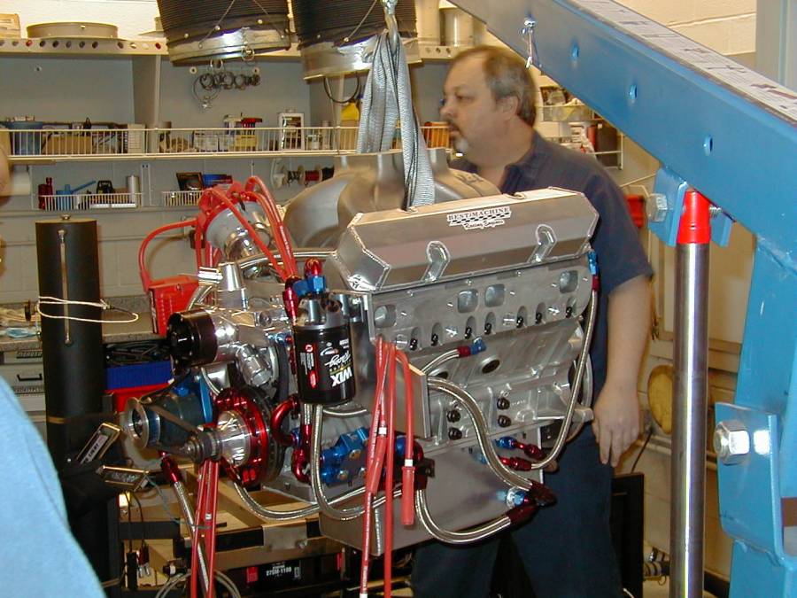
This. I was running -8 drainbacks lines from the front & back of the heads to the pan, and the pan was a custom pan with a lot going on inside, but can't remember the name of the vendor, but it wasn't cheap. At the time I was running Moroso's big enhanced 4-vane vac pump. Drainback was not an issue. Chuck put the regulator in the custom valley tray, and everything worked great.
Posted By: Al_Alguire
Re: 572 B1 org Part 5 - Build Notes - 01/01/22 06:33 PM
Any vacuum will fight the drain back, just science

Some pans are better designed than others for sure, oil control is an issue for sure especially with some pans.. That's a pretty big pan you had there. We run 8qt pans and of course run vacuum pumps and try to get every inch we can out f them. My current B1 deal is now pulling 17ish inches of vacuum. We always run -8 return lines as well, with a good pan and scraper that we make, only way to get it as close as possible to the crank.
We have the same issue in the Vette with its wet sump system. Heads we use are like B1 stuff in that they use drainback lines, we also have drainback lines in the valley of the block. We pull as much vacuum as we possible can and for a wet sump it does well at 20ish. We run as little oil as we can in that deal as well and its 0 weight oil at 7 qts when racing. On the dyno we have to run as much as 11 qts in the pan to keep oil in the thing. We dont beat it up on the dyno though as its just a tool and changes are always needed in the car to make it happy. We just get a feel for timing and peas, usually no more than 5-6 pulls.
Posted By: 440Jim
Re: 572 B1 org Part 5 - Build Notes - 03/09/22 04:43 PM
I tried making a You-Tube video showing one of my oil system tests.
This is the assembled engine, except one pair of lifters are removed to view the oil flow through the small (0.030"-0.035") hole in the lifter bushings.
I was using a slow (600 rpm max) battery powered hand drill to turn the oil pump, 64 psi with these lifters removed. Nice to know oil pressure exists even with lifters removed.
Plenty of flow though that little hole !
YouTube LINK to oiling testI also placed a set of pushrods in the lifters (no rocker arms) to make sure it pumped oil to the rockers/heads. Successful, but my video is too dark for a good view. The oil flowed out the rocker end of the pushrods, but did not shoot out like in the lifter bore. There was no pressure on the pushrods except their own weight resting in the lifter cup.
Posted By: Al_Alguire
Re: 572 B1 org Part 5 - Build Notes - 03/09/22 06:43 PM
We run the restrictors a bit tighter than yours is and never had an issue. Juts trying to keep oil down low.I have been down to .025". On ereason for the bushings is what you just found. Toss a liter from a broken rocker or badly broken spring and you still have pressure. The problem then will be the link bar. Why I like to use keyway stuff but overkill for most everyone.
Things happen when racing.
![[Linked Image]](https://i.postimg.cc/T270gwMs/88-F38-AFC-AC59-418-F-A2-ED-8-CF94518-D213.jpg)
Posted By: 440Jim
Re: 572 B1 org Part 5 - Build Notes - 03/10/22 06:20 PM
Before I put the rocker arms on the heads, I took this video showing the oil flow at the top of the pushrods.
https://youtu.be/LDWOWz-FtgcComp Cams 892 roller lifters
All lifters in place, using a slow (600 rpm max) battery powered hand drill to turn the oil pump, 66psi.
And with the rocker arms installed, oil flowed into the rockers and out the hole at the roller tip.

Posted By: 440Jim
Re: 572 B1 org Part 5 - Build Notes - 04/25/22 09:13 PM
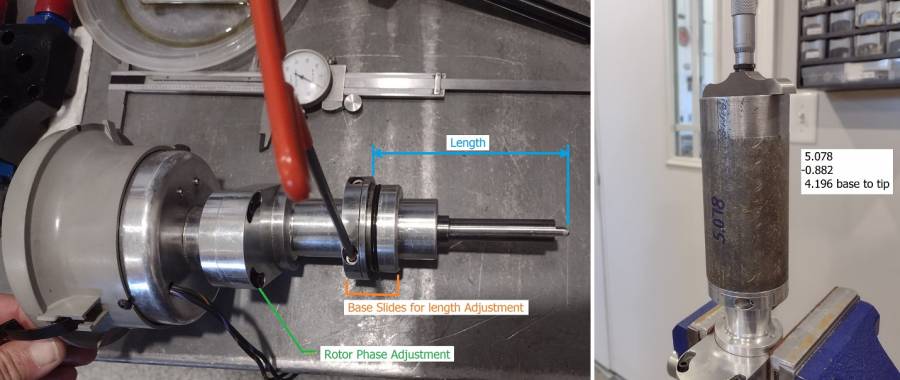
Part 5 – Offset Distributor. Build NotesI decided to keep the MSD distributor with the old Daytona cast iron engine. That mild engine used a custom advance curve (springs, etc). So, I needed one for the new B1 engine and found a lightly used offset distributor made for Predator heads. It moves the distributor cap away from the head and uses a large diameter cap (Ford style).
1) It has adjustable rotor phasing.
2) The base (with o-ring) is adjustable for shaft length as it clamps to the bearing housing part of the distributor
When I bought it, the tip of the shaft was 4.196” from the base (where it touches the block). I loosened the two allen head bolts that clamp the base to the distributor and installed it in my block with the bronze gear oil pump drive shaft that I am using (Milodon 21525). I pressed the assembly to bottom in the gear tang slot and tightened the allen bolts. I removed it and the zero endplay length was 4.176”. I made a small adjustment to give me 0.007” endplay; resulting in a length of 4.169”.
Posted By: 440Jim
Re: 572 B1 org Part 5 - Build Notes - 04/25/22 09:19 PM
FWIW,
I measured my old MSD "billet" distributor and the length sticking out was 4.080"
I measured my friend's new MSD distributor and the length sticking out was 4.106"
Posted By: Al_Alguire
Re: 572 B1 org Part 5 - Build Notes - 04/26/22 05:20 PM
I have an offset one in my 540" B1 in the Savoy as well. Not any issues with it and I like the larger cap. I usually use front drive distributors for the same reason.
![[Linked Image]](https://i.postimg.cc/FsR2zNJ4/1-D99-CD92-EA76-4-B20-B1-AB-78172-C28-C54-B.jpg)
Posted By: JohnRR
Re: 572 B1 org Part 5 - Build Notes - 04/26/22 07:27 PM
I tried making a You-Tube video showing one of my oil system tests.
This is the assembled engine, except one pair of lifters are removed to view the oil flow through the small (0.030"-0.035") hole in the lifter bushings.
I was using a slow (600 rpm max) battery powered hand drill to turn the oil pump, 64 psi with these lifters removed. Nice to know oil pressure exists even with lifters removed.
Plenty of flow though that little hole !
YouTube LINK to oiling testI also placed a set of pushrods in the lifters (no rocker arms) to make sure it pumped oil to the rockers/heads. Successful, but my video is too dark for a good view. The oil flowed out the rocker end of the pushrods, but did not shoot out like in the lifter bore. There was no pressure on the pushrods except their own weight resting in the lifter cup.
That's a good amount of flow , I had bigger holes put in my bushings, maybe too big looking at this??? I'll have to try this test when I get it together to see how bad it is .
Posted By: Craig J
Re: 572 B1 org Part 5 - Build Notes - 09/03/22 02:11 AM
I apologize if I missed it, but what did you do with the rear seal on this engine? Great detail in you summary, thank you, Craig.
Posted By: ProSport
Re: 572 B1 org Part 5 - Build Notes - 09/04/22 03:50 PM
Some really good info in this thread. Thanks for posting the oiling videos Jim.


![[Linked Image]](https://i.postimg.cc/T270gwMs/88-F38-AFC-AC59-418-F-A2-ED-8-CF94518-D213.jpg)


![[Linked Image]](https://i.postimg.cc/FsR2zNJ4/1-D99-CD92-EA76-4-B20-B1-AB-78172-C28-C54-B.jpg)