Moparts
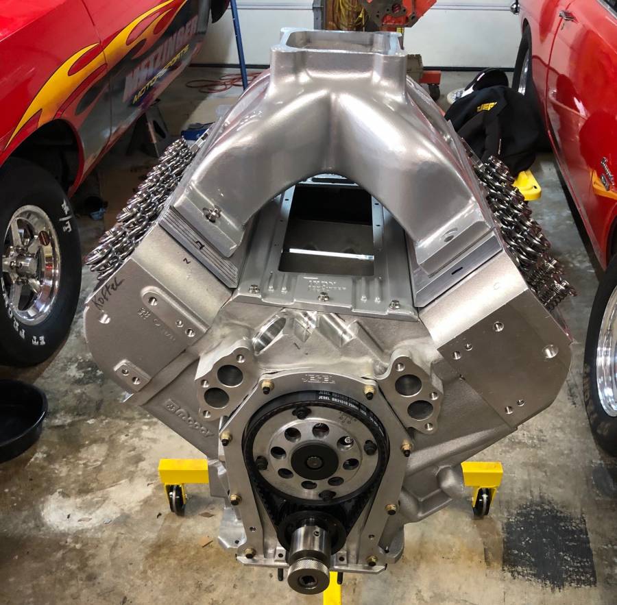
508” KB – B1 build
Just thought I’d share my build with you guys. My car has been parked for 4 years while I focused on Jr dragster racing with my daughter and saving for parts to put this motor together.
Intake spacers are being fitted (what a pain in the butt) and the pistons and rods are back in production as the manufactures go back to production.
I'll still footbrake but my focus is mainly on NHRA 10.90 SST racing.
Let me hear your thought/opinions/questions on my build.
Block
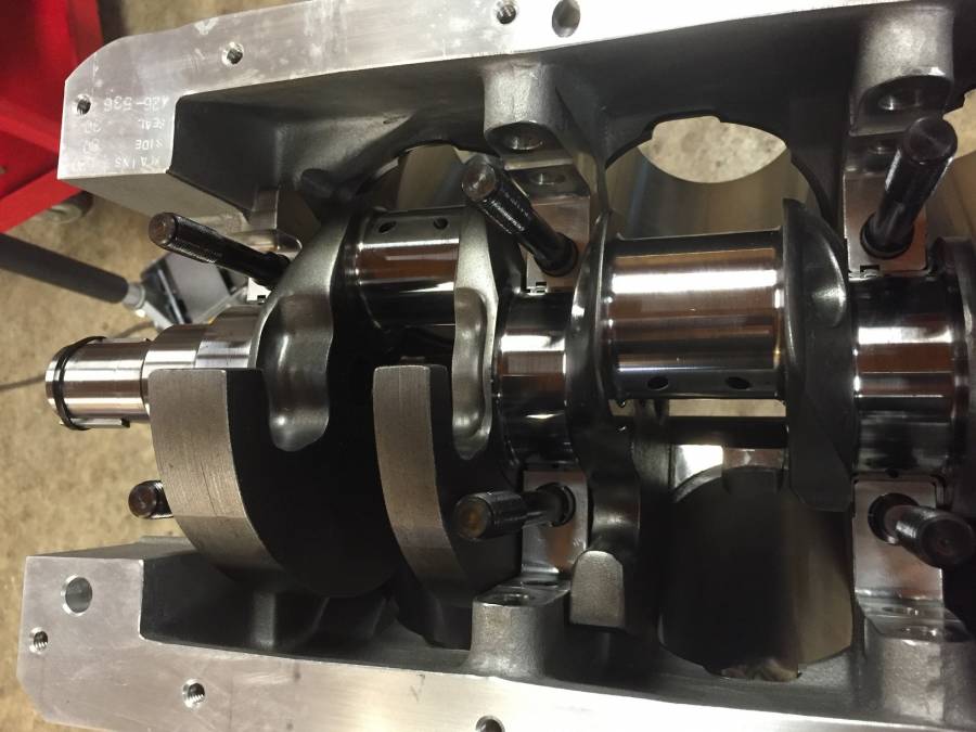
- Keith Black aluminum RB 10.725” deck wet bock from 2014 (I think 440Jim and I were the last ones to get their blocks before they shutdown)
- Drilled lifter galley and tapped for oil restrictions
- Drilled for oil line access on top/back of block.
Heads
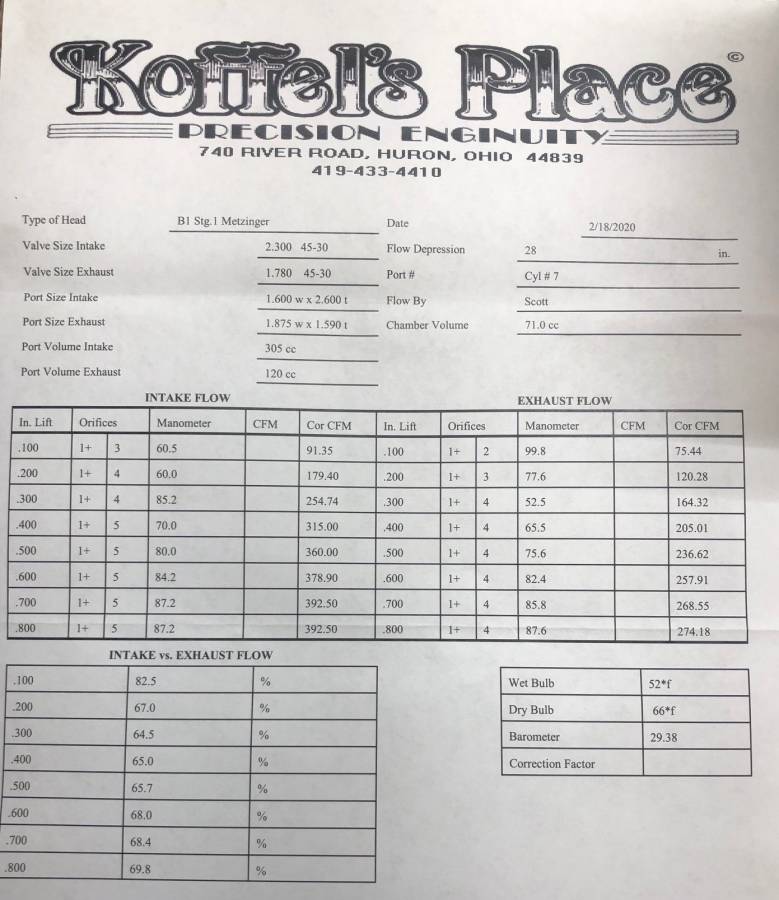
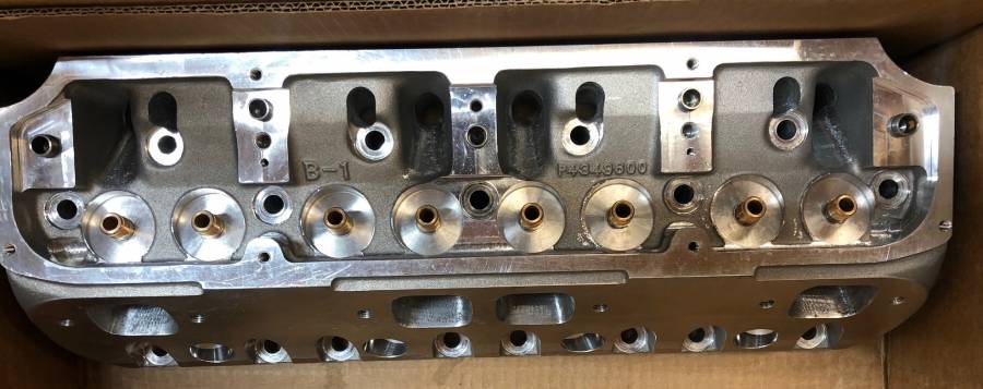
- B1 originals, Stage 1 hand porting by Scott Koffel, Ti Intake valves, T&D 1.7 rockers, flow 392 at .700 on Koffel’s flow bench
Intake
- B1 low deck intake with spacers (what a pain in the butt!!!)
Cam
- Strange Magic solid roller 4/7 swap .767/.767 276/288 110 Lobe Sep 180 Intake centerline
- Isky EZ-Roll Solid Bushing lifters
- Jessel Belt drive
Rotating Assembly
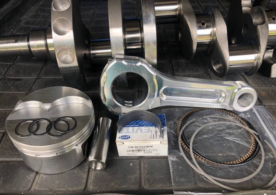
- Callies Magnum XL 4.25” with 2.100” rod journals
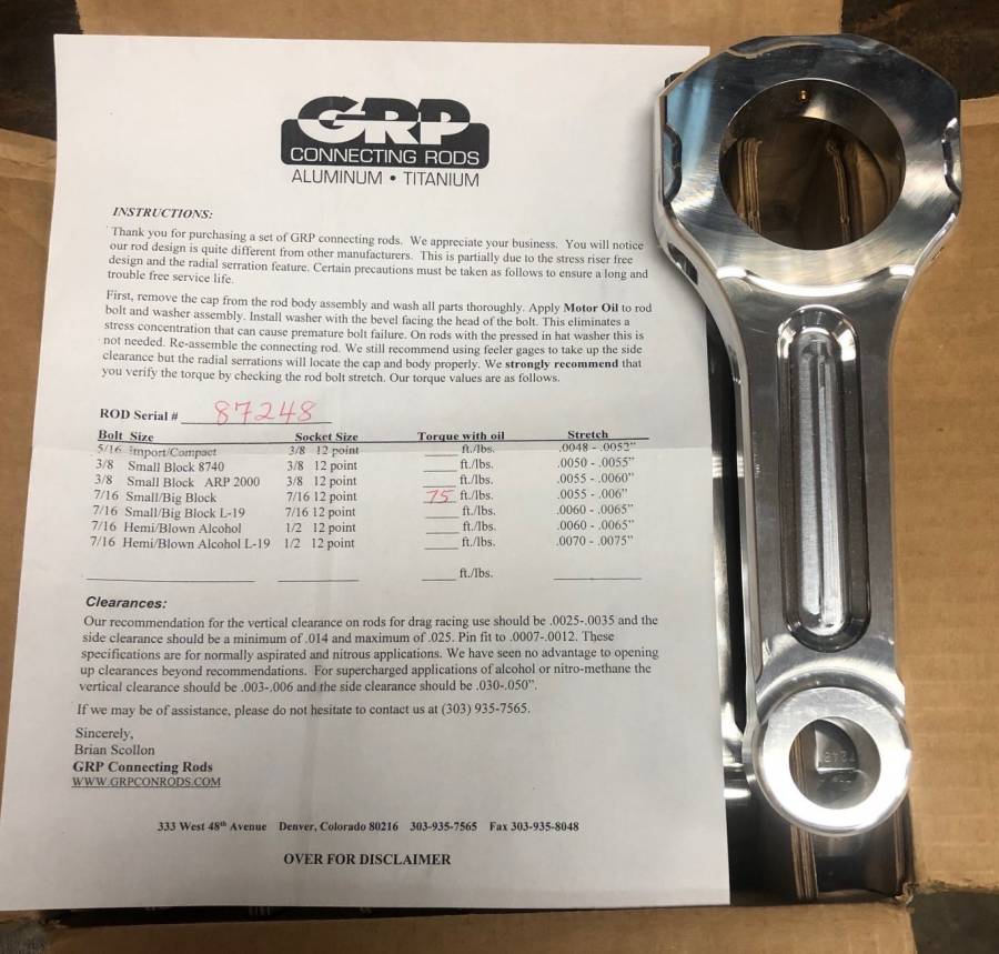
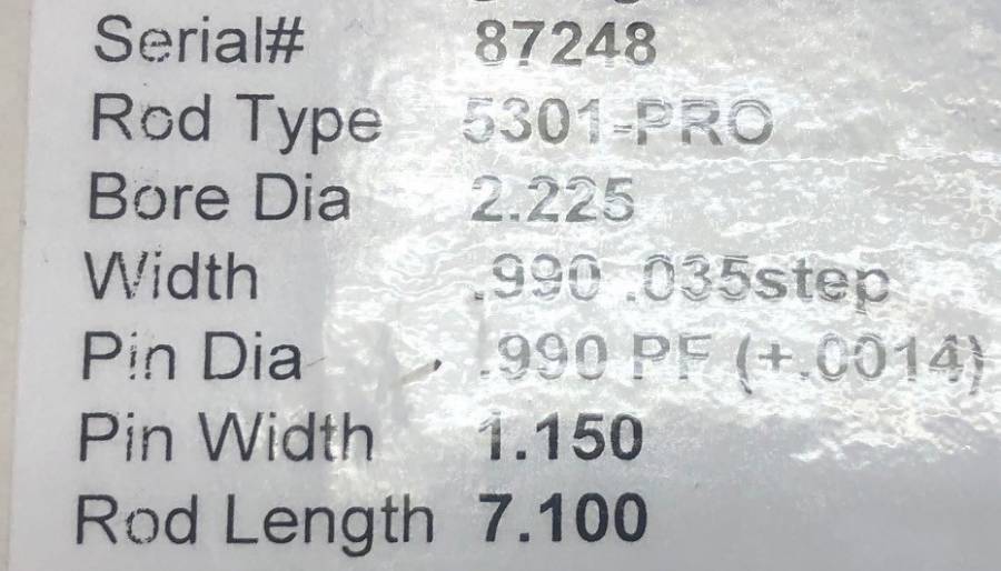
- GRP Rods 7.100”
- Diamond Pistons 4.360”, gas ported, .043 rings, tool steel pins --- 13.2:1 compression ----
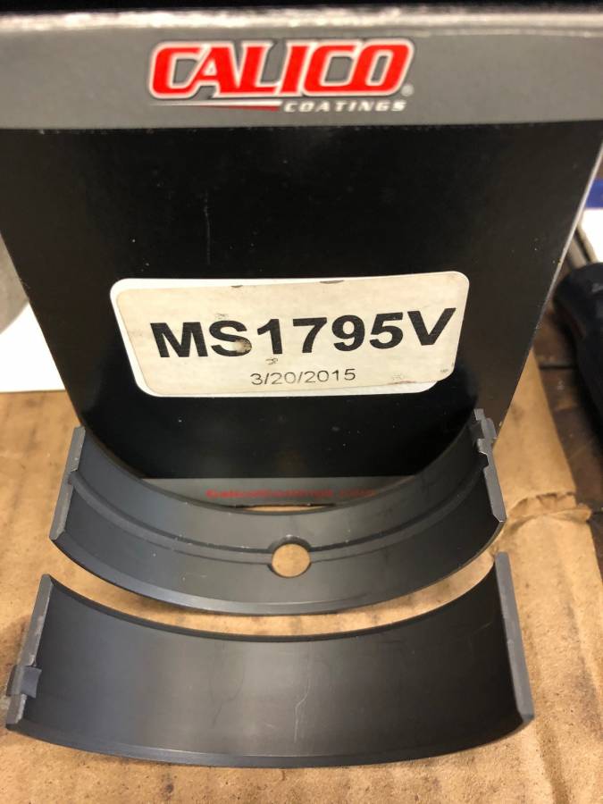
- Coated Clevite sbc rod and Calico coated main bearing
Carb
- APD Max Speed billet carb, 1175 Gas or 1150 Alky (still trying to decide which way to go, I’ve been running alcohol for 20 years, my wife and daughters Jr both use alcohol so that would be carrying 2 different fuels, it will probably cost more and keeping it cool when double entering will be challenging.
Driveline
- PG (JW bell, JW case, BTE 1.80)
- 3.5” Strange Chromoly driveshaft with billet yokes and 1350 u-joint
- Dana 60 with Richmond 4.56 Pro gears
- Strange 35 spline axles
- Strange dual caliper brakes
Tires
- MT 14x32 Pro Bracket Radials
Posted By: birdtracker
Re: 508” KB – B1 build - 04/23/20 09:07 PM
first I doubt you will have to run that engine hard to go 10.90. 2nd how easy was the intake spacers. Everyone says they are a piece of cake!!!!!! Birdtracker
Posted By: WadeMetzinger
Re: 508” KB – B1 build - 04/23/20 09:33 PM
Hoping it will run 10.90s at mid 140mphs (need to stay away from 150 as i don't have a chute).
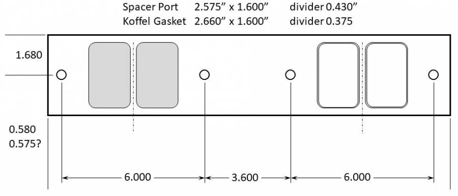
The port on the spacer were smaller than the ports on the heads and intake and then getting all that lined up plus 2 gaskets was challenging so I called in a favor of a buddy with a Bridgeport and he's taking care of all that for me. (I hit the "Easy" button) In the future I'll probably have them welded up.
The thing that makes the intake spacers fun is it's not one angle. It's kinda like one angle going into the head and one into the intake manifold times 2. So 16 angles worth of work but it can be a thing of beauty when finished. On my build I had more work getting the pushrod clearance opened up.
Posted By: WadeMetzinger
Re: 508” KB – B1 build - 04/23/20 09:55 PM
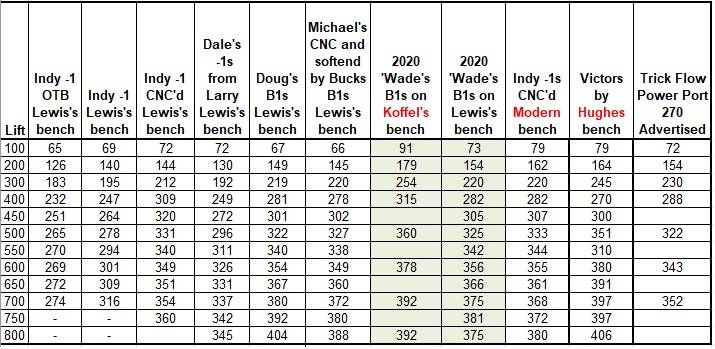
Here are some flow bench numbers of several sets of heads I've had access to over the years. Jim Lewis is a local, but nationally know head porter of stocker head, so I use his bench so I can compare apples to apples. His bench is a little stingy but it makes it possible to compare different heads.
Posted By: sasquatch
Re: 508” KB – B1 build - 04/23/20 09:59 PM
Wade that thing should go 10.90 in reverse...How much weight are you dragging? Todd
Posted By: WadeMetzinger
Re: 508” KB – B1 build - 04/23/20 10:27 PM
pittsburghracer - the Stage 1 porting included push-rod clearancing, i made sure to discuss that with Scott.
Todd - I think it will be 3,200lbs race weight. Fiberglass hood, doors, deck and lexan windows but it's still just a backhalf car with mild steel cage
Posted By: racerx
Re: 508” KB – B1 build - 04/24/20 01:48 AM
What kind of car? It's not the cuda is it?
Curious as to why you chose the 4.360 bore vs. 4.50 bore size?
Posted By: WadeMetzinger
Re: 508” KB – B1 build - 04/24/20 01:24 PM
I went with 4.360 bore for a few reasons, mainly because if had I a failure, I may be able to just bore cylinders out and keep on going without having to replace sleeves. I took this approach on my Mega block and was able to bore from 4.350 to 4.440 when I broke a rod and then 4.440 to 4.50 when I dropped a valve. I also had a really nice set of Diamond pistons that were 4.360 that I was planning to use but when I decided to move to B1s, I had to buy new pistons. I asked Scott Koffel about the bore and he said it would be fine. I'm don't need 1,000hp so not trying to get every HP out of it. (I had Ken Black put the 4.5" darton sleeves in the block so they are just super super thick as they weren't the normal 4.5" sleeve they typically use.)
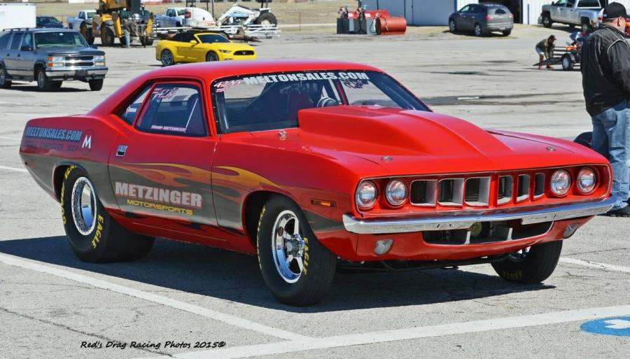
Yes, this is going in my 1971 Barracuda
Question for you guys, will I be able to use my header that I've been running with Indy -1s? (they are 2 1/4 so plenty big enough, just wasn't sure if they exhaust ports moved up or down from the -1s)
Posted By: bobby66
Re: 508” KB – B1 build - 04/24/20 02:17 PM
Fine looking machine right there!

Posted By: Cab_Burge
Re: 508” KB – B1 build - 04/24/20 05:12 PM
Your going to have to try the headers, my car was the opposite do to it having a B1 motor in it before, those headers are 2 1/8 to 2 1/4 step and they fit and worked fine on the M.W. Victors and the new motor with the ported 440-1. I did have to dent them to clear the front frame tubes, it is a chrome moly tube chassis car, do to using a stock 400 block.
If yours won't work I may have another race set that will work in a stock chassis car

PM me if you need to

Posted By: 440Jim
Re: 508” KB – B1 build - 04/24/20 05:31 PM
Intake spacers are being fitted (what a pain in the butt) and the pistons and rods are back in production as the manufactures go back to production.
Block
- Keith Black aluminum RB 10.725” deck wet bock from 2014 (I think 440Jim and I were the last ones to get their blocks before they shutdown)
- Drilled lifter galley and tapped for oil restrictions
- Drilled for oil line access on top/back of block.
Intake
- B1 low deck intake with spacers (what a pain in the butt!!!)
I look forward to hearing how your engine build goes. Are you going to dyno test it?
My block was s/n 426-538 and yours is 426-536, so very close together in Ken's shop. I was happy with his machine work on the block. Bore, deck height, mains, etc.
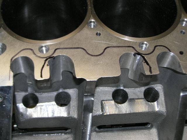
I expect you will have to clearance the block for the pushrods, my 440-1 heads needed a little more then Ken machined the block. My head opening is traced, but I only needed a little with the grinder right where my pushrod was touching (look carefully at my pic for the grinder).
I may have told you about my experience with the oil to the lifter galleys. Back then his blocks had the oil going around the rear cam bearing to the rear holes for the lifter galley. That special groove around the outside of the cam bearing was a nice restrictor and I didn't need any additional oil restricting for push rod oiling. I put an oil pressure gauge on the main oil supply galley (priority main oiling) and a second gauge on the top/back of the block while priming the system on the engine stand. Are you using spray bars for the B1 heads?
The one set of B1 intake spacers I saw had very small openings, and significant variation from one port to the next. A lot of material to remove, and the angled intake manifold bolt holes and port angles may need a hand grinder for final work after milling the spacers a little closer to size. This is what I saw (pic).
Posted By: 440Jim
Re: 508” KB – B1 build - 04/24/20 06:31 PM
Question for you guys, will I be able to use my header that I've been running with Indy -1s? (they are 2 1/4 so plenty big enough, just wasn't sure if they exhaust ports moved up or down from the -1s)
Trying to get more details from others for you.
Koffel's web site says, "The raised exhaust ports will accept a stock header flange."
The question is how much are these raised? (Compared to your previous Indy 440-1 heads)I saved this from a post by TTI years ago,
The Brodix are 3/4" wider and 3/4" taller than a stock iron head. The Indy heads are 7/16" taller and 5/8" wider than the stock iron head.
Posted By: LA360
Re: 508” KB – B1 build - 04/25/20 01:30 AM
They do a tall deck version of the B1 intake these days? The spacers are a pain, I helped a friend with his, we bolted his to the head with sealer.
I went with 4.360 bore for a few reasons, mainly because if had I a failure, I may be able to just bore cylinders out and keep on going without having to replace sleeves. I took this approach on my Mega block and was able to bore from 4.350 to 4.440 when I broke a rod and then 4.440 to 4.50 when I dropped a valve. I also had a really nice set of Diamond pistons that were 4.360 that I was planning to use but when I decided to move to B1s, I had to buy new pistons. I asked Scott Koffel about the bore and he said it would be fine. I'm don't need 1,000hp so not trying to get every HP out of it. (I had Ken Black put the 4.5" darton sleeves in the block so they are just super super thick as they weren't the normal 4.5" sleeve they typically use.)
Yes, this is going in my 1971 Barracuda
Question for you guys, will I be able to use my header that I've been running with Indy -1s? (they are 2 1/4 so plenty big enough, just wasn't sure if they exhaust ports moved up or down from the -1s)
Thanks for the explanation.
Posted By: 440Jim
Re: 508” KB – B1 build - 04/25/20 01:56 PM
The spacers are a pain, I helped a friend with his, we bolted his to the head with sealer.
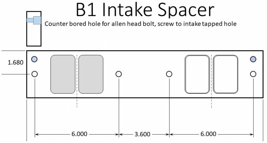
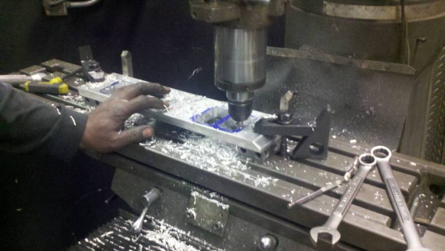
Along that line of thinking. I thought machining a counter bored hole in the spacer for an allen head bolt to allow screwing it to a matching threaded hole in the intake manifold. Then whenever the engine is taken apart, you just leave the intake and the spacers screwed together. And the final hand porting is done with the spacer screwed to the intake for a perfect match. The blue holes are what I am thinking. It doesn't need big allen head bolts, maybe 1/4", since the clamping is done by the original 3/8" intake bolts. Just enough to keep it together in the same location.
Posted By: Cab_Burge
Re: 508” KB – B1 build - 04/25/20 05:45 PM
The spacers are a pain, I helped a friend with his, we bolted his to the head with sealer.
Along that line of thinking. I thought machining a counter bored hole in the spacer for an allen head bolt to allow screwing it to a matching threaded hole in the intake manifold. Then whenever the engine is taken apart, you just leave the intake and the spacers screwed together. And the final hand porting is done with the spacer screwed to the intake for a perfect match. The blue holes are what I am thinking. It doesn't need big allen head bolts, maybe 1/4", since the clamping is done by the original 3/8" intake bolts. Just enough to keep it together in the same location.
I would do that also but I would put the two holes under the center two intake bolts or beside them


My spacers plates are held in position with little split pins and I stamped them for port position for fast identification. Nothing fancy and works great.
.
Posted By: Al_Alguire
Re: 508” KB – B1 build - 04/25/20 07:33 PM
They do a tall deck version of the B1 intake these days? The spacers are a pain, I helped a friend with his, we bolted his to the head with sealer.
They only made a run of a few and Scott has no plans to make more of them, no matter how much I beg him too

Posted By: Jeepmon
Re: 508” KB – B1 build - 04/25/20 08:03 PM
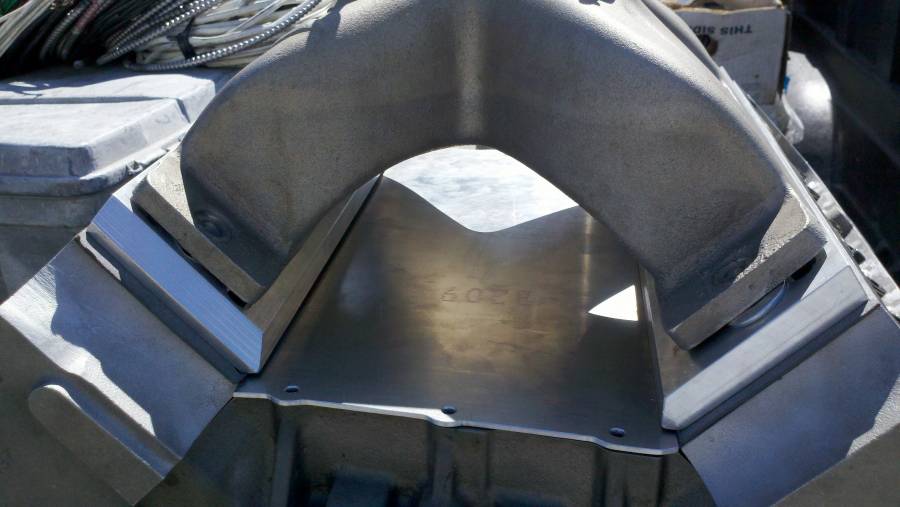
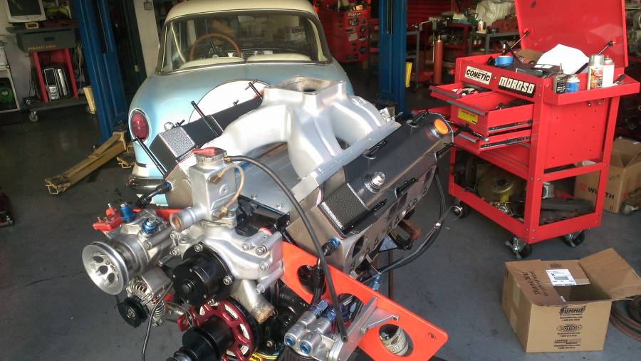
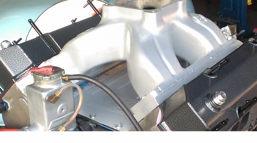
I didnt care too much for the B1 tall deck spacer, so instead of setting pins, or trying to bolt them together, I just port matched and welded them to the bottom of the intake... The end result is great and I never think twice about it now...
If I did the attachments properly, I have included pics of the intake and spacer
Posted By: Jeepmon
Re: 508” KB – B1 build - 04/25/20 08:06 PM
Better pic
Posted By: markz528
Re: 508” KB – B1 build - 04/25/20 09:54 PM
I didnt care too much for the B1 tall deck spacer, so instead of setting pins, or trying to bolt them together, I just port matched and welded them to the bottom of the intake... The end result is great and I never think twice about it now...
Tony Bischoff did a similar thing to mine but he cut them all the way off and welded the spacers to the runners. Came out great. Don't have ant pics.
Posted By: AndyF
Re: 508” KB – B1 build - 04/25/20 10:14 PM
It seems weird that Koffel has never tooled up an RB version of that intake manifold. Those heads have been around for 30 years and the RB block is 10x more popular than the B block. They would've paid for the tooling many times over by now.
It seems weird that Koffel has never tooled up an RB version of that intake manifold. Those heads have been around for 30 years and the RB block is 10x more popular than the B block. They would've paid for the tooling many times over by now.
m
Ya but this way they sold intakes AND spacers. Profit on both ends. Lol.
Posted By: n20mstr
Re: 508” KB – B1 build - 04/25/20 11:29 PM
It seems weird that Koffel has never tooled up an RB version of that intake manifold. Those heads have been around for 30 years and the RB block is 10x more popular than the B block. They would've paid for the tooling many times over by now.
they did have some made, Gary Robbins has one. Dont know if it is still availible
Posted By: 440Jim
Re: 508” KB – B1 build - 04/26/20 09:28 PM
They do a tall deck version of the B1 intake these days? The spacers are a pain, I helped a friend with his, we bolted his to the head with sealer.
They only made a run of a few and Scott has no plans to make more of them, no matter how much I beg him too

I don't know Scott Koffel, but he can sell the low deck intake for $500 and get another $300 for the spacers, that is an $800 cast RB intake. Good money...

Posted By: WadeMetzinger
Re: 508” KB – B1 build - 04/27/20 03:38 PM
I look forward to hearing how your engine build goes. Are you going to dyno test it?
My block was s/n 426-538 and yours is 426-536, so very close together in Ken's shop. I was happy with his machine work on the block. Bore, deck height, mains, etc.
I expect you will have to clearance the block for the pushrods, my 440-1 heads needed a little more then Ken machined the block. My head opening is traced, but I only needed a little with the grinder right where my pushrod was touching (look carefully at my pic for the grinder).
I may have told you about my experience with the oil to the lifter galleys. Back then his blocks had the oil going around the rear cam bearing to the rear holes for the lifter galley. That special groove around the outside of the cam bearing was a nice restrictor and I didn't need any additional oil restricting for push rod oiling. I put an oil pressure gauge on the main oil supply galley (priority main oiling) and a second gauge on the top/back of the block while priming the system on the engine stand. Are you using spray bars for the B1 heads?
The one set of B1 intake spacers I saw had very small openings, and significant variation from one port to the next. A lot of material to remove, and the angled intake manifold bolt holes and port angles may need a hand grinder for final work after milling the spacers a little closer to size. This is what I saw (pic).
Jim, I'll be careful to check for pushrod clearance as you pointed out.
I've haven't totally decided on plan for head/rocker/push rod oiling. I was originally planning to do do pushrod oiling but I'm now considering just using the standard oiling up through the block and rocker stands through the shafts to the rockers and pushrods. I wouldn't have to buy special lifters or put restrictors in the pushrods. The B1 heads have a 10/32 in the rocker stands so I can put in a restrictor of like .060 and the adjuster screws in the rockers have oil holes in the cup to oil the pushrods. Scott recommended having the #4 cam journal grooved to it would oil all the time and not pulse oil, but also been told the pulse oiling is enough and full time will put too much oil in the top end, so still thinking about that decision. (not planning to use spray bar oiling)
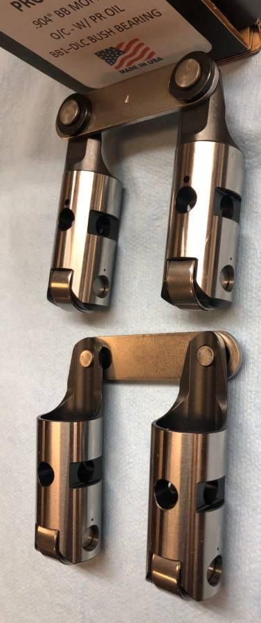
I had plan on going with Isky bushed lifters but I've learned of a different option that people are suggesting are even better design. BAM is making a roller lifter where they coat the pin with some coating that is harder than steel and eliminates the need for needle bearings and bushings. So without those the roller and the pins can be thicker. My understanding is this technology came from NASCAR. Doing some research on this before buying.
Regarding the intake spacers, the new spacers that come from Koffel already have a counter sunk hole in them so you can drill and tap the head for a cap screw so that was a nice improvement.
Posted By: WadeMetzinger
Re: 508” KB – B1 build - 04/27/20 03:41 PM
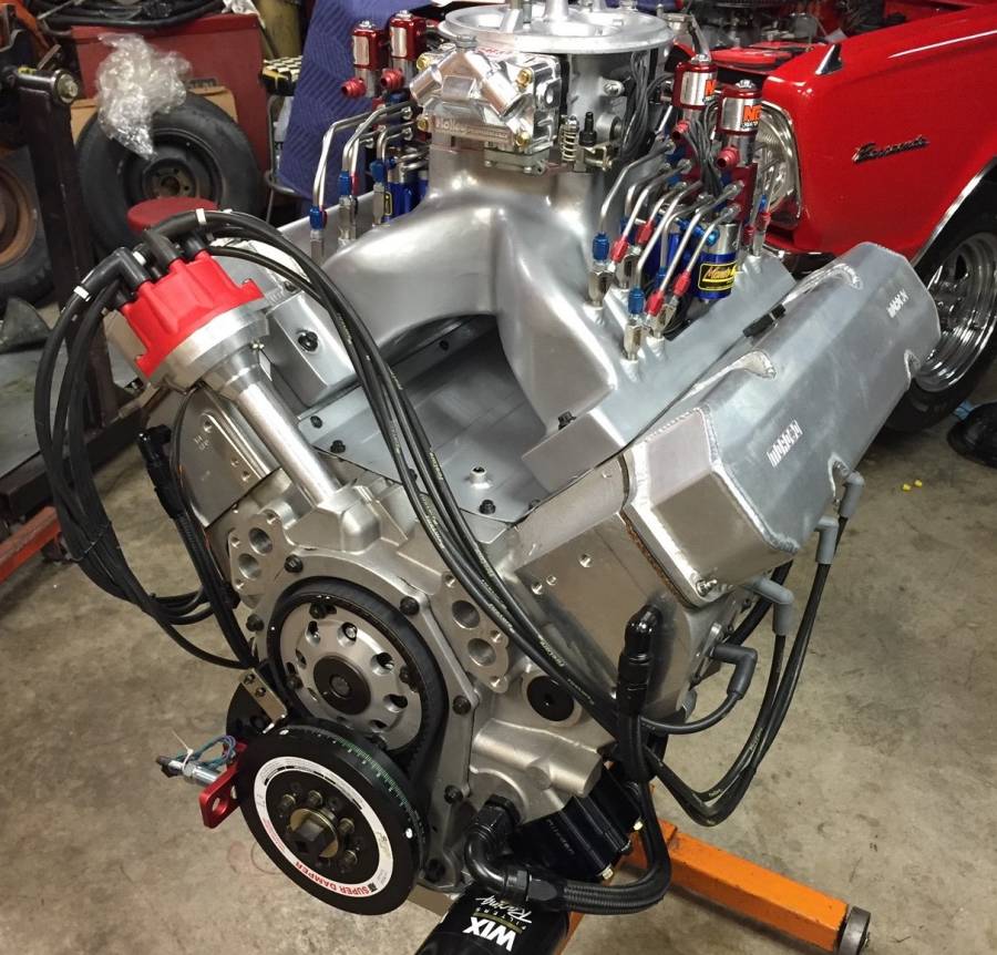
Here is a picture of a welded intake for a Drag Week motor I built for a customer 2 years ago. It was already done, i just used it and it worked great. It also had a 1" spacer added to the carb flange. (NOS plumbing done by Monte)
Posted By: 440Jim
Re: 508” KB – B1 build - 04/27/20 04:40 PM
Wade, that is a nice looking intake.
Somebody put work into making it look nice as well as work nice.
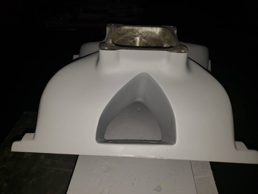
Here is one of the RB cast intakes
Posted By: Dodgeguy101
Re: 508” KB – B1 build - 04/27/20 07:26 PM
Here is one of the RB cast intakes
What does one of those intakes weigh? Looks plenty heavy.
Posted By: Al_Alguire
Re: 508” KB – B1 build - 04/27/20 09:28 PM
It seems weird that Koffel has never tooled up an RB version of that intake manifold. Those heads have been around for 30 years and the RB block is 10x more popular than the B block. They would've paid for the tooling many times over by now.
They do and they have, on a very limited basis with no plans to mass produce them or likely even making any limited runs of them.
Posted By: WadeMetzinger
Re: 508” KB – B1 build - 04/30/20 03:22 PM
Posted By: WadeMetzinger
Re: 508” KB – B1 build - 05/13/20 05:02 PM
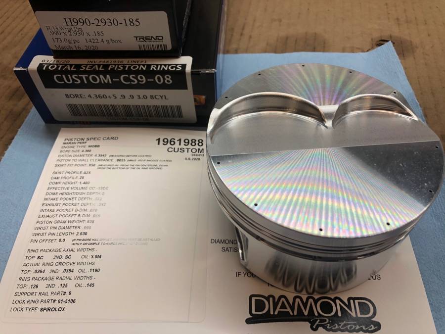
I finally received the pistons, they were ordered back in Feb but COVID-19 has held them up…
Now I’m just waiting on the GRP rods, they were ordered at the same time and GRP never shut down but I’m guessing they slowed down and we did get a call asking if we wanted Chevy or Mopar beam angle so I’m thinking they had them built and then had to scrap them and start over…
Decided not to coat them, there are some benefits but not sure they are worth the cost.
Upgraded the pins to H-13
Vertical Gas ported
.043/.043 rings (could have gone smaller but I'm not running vacuum pump so I thought this would give me some smaller ring pack benefits and not get in trouble going to thin and having to run vacuum pump)
- edit, I ordered .043 . 043 but it looks like they made them .9 .9 and 3mm... doh! the oil ring is 10# so I need to call Total Seal and find out if that will work without vacuum pump.
-->They said 10# wouldn't work so they are sending me a different oil ring expander to increase the pressure.
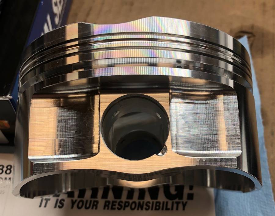
Update - When we ordered pistons we were shooting for 12.5:1 but I'm only getting about 11.5:1 and we think the problem could be that valve relief number they provided on the piston card, pretty hard to believe that there is a -13cc in just the valve relief. We were expecting 3 to 4 so that would cause me to loose a point of compression so I'm going to cc the pistons later today.
[list]
[*]10.725 deck
[*]4.360" bore
[*]4.25" stroke
[*]7.100" rod
[*]1.480" piston compression height (so i think that adds up to .020 in the hole)
[*].040 head gasket
[*]-13 cc piston valve reliefs
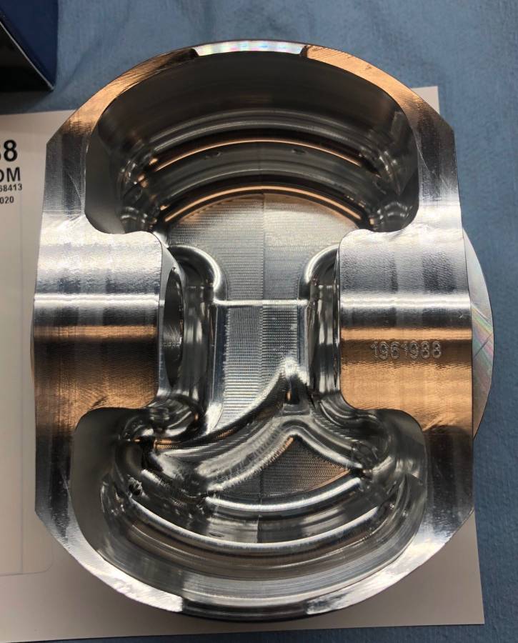
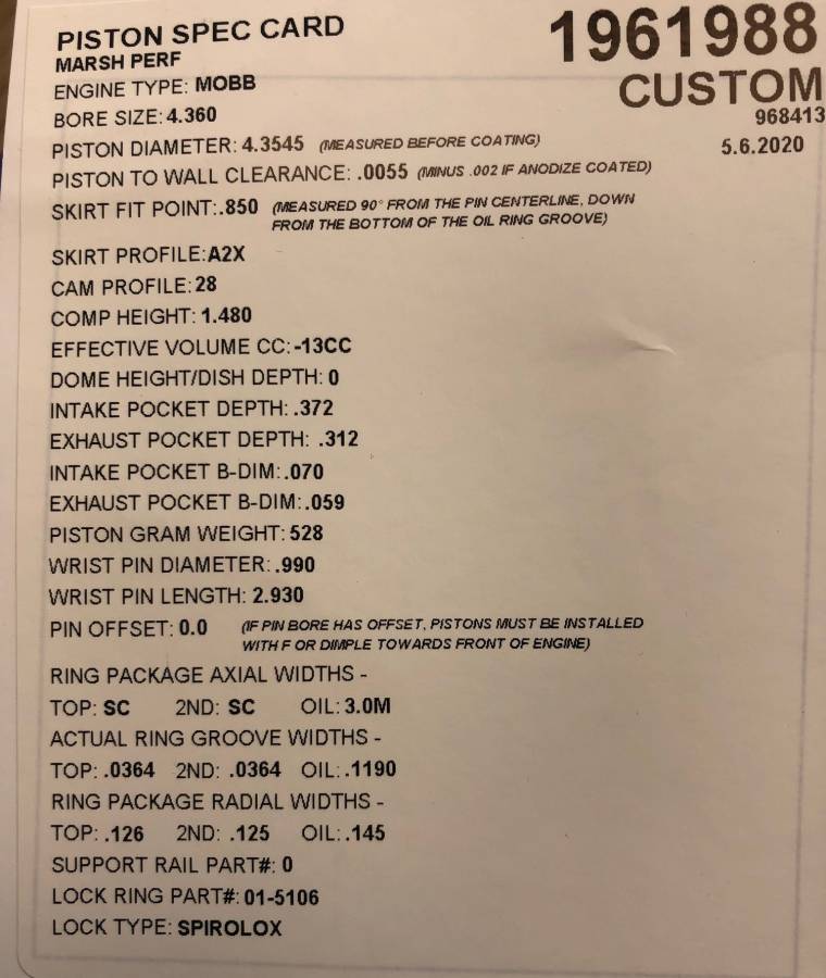
Posted By: WadeMetzinger
Re: 508” KB – B1 build - 05/13/20 05:06 PM
I have been running the Isky's with the bushing and most people consider them the best option over needle bearing roller lifters. I did some research and found out from several people and some serious engine builders that now the BAM lifters with the DLC pins are even superior to the bushing.
DLC is Diamond-Like-Carbon Laser Coated, I pulled this from the web "What is a Diamond-Like-Carbon (DLC) Coating? DLC coatings offer a unique combination of high hardness and low friction coefficient → 'the hardness of diamond and the lubricity of graphite'.
So now you don't have to worry about needle bearings failing or the bushing getting beat out. My research is showing this are our best option without going exotic. I got these for $1,130 to my door, which is about $300 less than Isky bushed lifters.
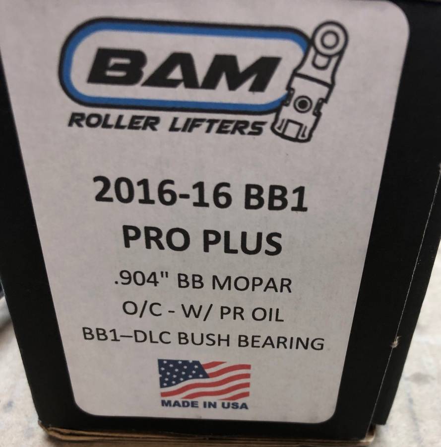
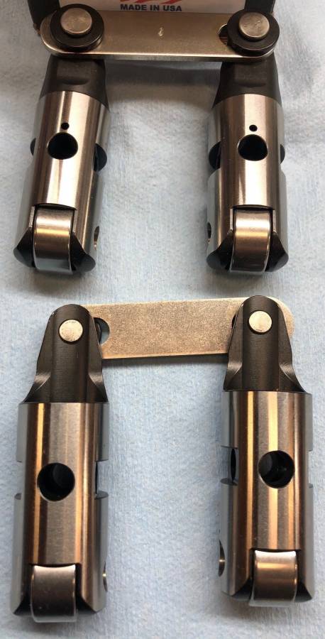
Posted By: Cab_Burge
Re: 508” KB – B1 build - 05/13/20 06:51 PM
I would mock up one or two pistons, rods and crankshaft at TDC,one on each side, and seal the piston tops to the cylinder wall( I use a small tip on my handheld grease gun) and then pour it to find out exactly the volume in each cylinders is to be able to figure out exactly what the compression ratio will be

I use that method on Hemiroid motors, I'll move the piston down (I use a dial indicator to get the down travel) so the dome is below the deck by .030 or .050 and then use my plastic CC plate to fill the bore up, I'll use the math for a flat top piston down the same amount in the cylinder and subtract the measure amount to get the dome volume


Big C.I. motors are a lot easier to get to much compression, unlike little C.I. motors that need big domes to get decent racing compression ratios

Posted By: Al_Alguire
Re: 508” KB – B1 build - 05/13/20 09:51 PM
BAM has a very good reputation with some very big names in the industry. I planned on trying them next time we build something. Having said that I have run Isky bushed red zones for a very long time with no failures. But I believe they are a bit more $$
Posted By: 440Jim
Re: 508” KB – B1 build - 05/13/20 10:54 PM
Update - When we ordered pistons we were shooting for 12.5:1 but I'm only getting about 11.5:1 and we think the problem could be that valve relief number they provided on the piston card, pretty hard to believe that there is a -13cc in just the valve relief. We were expecting 3 to 4 so that would cause me to loose a point of compression so I'm going to cc the pistons later today.
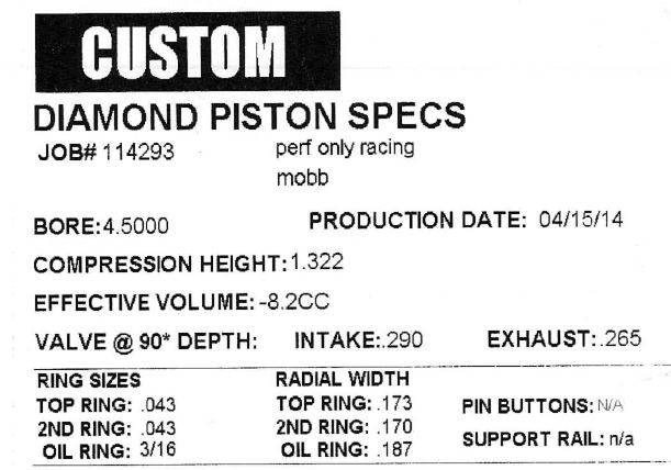
Back in 2014 when I had custom Diamond pistons for my 440-1 engine with 4.500" bore, the valve relief's were 8.2cc (Diamond's number). And my valve reliefs were smaller and not as deep as yours. I was expecting about 6cc, but that is what the sheet said.
Intake: 0.290" depth, 2.3" dia relief
Exh: 0.265" depth, 1.84" dia relief
Posted By: WadeMetzinger
Re: 508” KB – B1 build - 05/13/20 11:51 PM
I checked the cc on the piston by wrapping it with saran-wrap, then packing tape and then sliding it down into my 4.360 ring compressor to keep it level and still. I put my 20cc's in my syringe and it took 20cc to fill it up. I can't control the bubble effect that goes above the surface but that would only account for 1 or 2cc's so they are at least 13cc's.
My 3 options are:
- Deck the block or use .020 head gasket
- Surface the heads (Scott Koffel said .006 was worth 1cc so I'd have to take off .060 and .060 off the intake)
- Remake pistons
I hate having to wait another 6 or so weeks but I think that is the option that makes the most sense.
Posted By: 440Jim
Re: 508” KB – B1 build - 05/14/20 01:03 AM
I can't tell you which way to go, it is your decision.
But from my limited experience, you don't need the valve reliefs as deep as your's are spec'd.
FWIW:
My 440-1 setup is not the same as your B1-MC, but I was running a cam with 0.750" lift, 279/290 duration at 0.050", 112 LSA, installed intake CL 108.
My piston to valve clearance came out to 0.155"/0.231" (int/exh) with 0.014"/0.020" cold lash for checking purposes. Again, valve relief depths were 0.290"/0.265"
Posted By: Cab_Burge
Re: 508” KB – B1 build - 05/14/20 01:55 AM
All the B1 and B1-MC pistons I've seen had really deep valve reliefs in them, all of them

I'll be going through this process, having pistons made, on one of my B1 headed motors, hopefully this summer if we can get our country out of this mess with the economy and parts making problems

Posted By: Cab_Burge
Re: 508” KB – B1 build - 05/14/20 01:57 AM
If you use the .020 head gaskets what piston to head clearances will you have? Allso what compression ratio?
Posted By: 440Jim
Re: 508” KB – B1 build - 05/14/20 01:15 PM
All the B1 and B1-MC pistons I've seen had really deep valve reliefs in them, all of them

It would be helpful if somebody with B1 heads could post actual piston to valve clearance with known valve reliefs and cam specs, since that plays a big part in P2V.
Posted By: WadeMetzinger
Re: 508” KB – B1 build - 05/14/20 04:03 PM
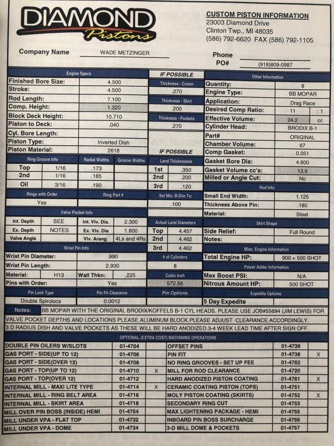
Here are the details of the Drag Week 572 B1 motor I built:
11.3:1 compression for pump gas and then 600-750 Nitrous
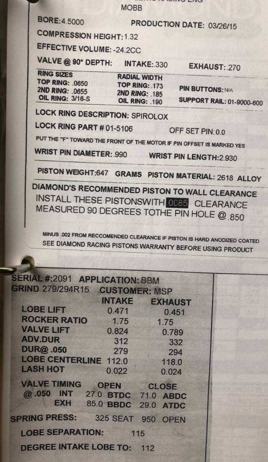
Diamond Pistons 1.32 compression height and 24.2cc dish, valve depth at 90* intake: 330 and exhaust 270 picture of card and order form below
Cam designed by Monte Smith for this motor: .824/.789 lift with 1.75 pair T&D rockers (.471/.451 lobe lift), 279/294 duration, 112 Intake center line, 115 lob separation cam card pic below
I didn't write down the exact minimum clearance because I had more than .150 at 10 before and 10 after. Since we had a Jessel belt drive and we could adjust the cam degree easliy we did check it at a few different places but left the cam installed at 112.
For my pistons we didn't spec the valve pockets, we just used an off the shelf piston part #, changed the ring pack and told them to adjust valve pockets for B1 heads but they were supposed to keep the 4cc to keep 12:1 compression target. I'm guessing they may need to put a little dome on top side of the piston or they may want to decrease compression height from 1.480"
Posted By: Cab_Burge
Re: 508” KB – B1 build - 05/14/20 05:26 PM
Do you know how much piston to head clearances you have across the tops of the pistons?
If not, you should :scope :

I use to believe that the old adage of .035 minimum with steel rods was good until I found out ii isn't


I like and use .040 minimum now with steel rod motors

Posted By: 440Jim
Re: 508” KB – B1 build - 05/14/20 05:27 PM
Since that Drag Week B1 engine had over 0.150" P2V with 0.330"/0.270" deep valve pockets, I don't see the need for the -13cc pockets they put on your pistons (0.372"/0.312").
Posted By: Al_Alguire
Re: 508” KB – B1 build - 05/14/20 05:34 PM
Those reliefs look pretty typical to me for a B1 head. Part of your issue is going to be the smaller bore which will cause those reliefs to take up a lot of real estate. I don't think if you ask Scott he would say that small bore is ideal for those heads by any means. What compression ratio are you shooting for. Typically you should end up with a net zero piston or close once the reliefs are countered by a small dome to get a typical "race engine" compression, for me that mean 15ish to 1 fwiw. I have done some 12/13-1 stuff like my Valiant was, piston looked pretty much like yours do, valve reliefs around 13-18 and flat top. You will end up with somewhere around that 13-18cc relief and be 12/13ish to 1 depending on how small the chamber is. I don't have those pics handy. Also did a B1 original that came in at 14-1, again sorry no pics. But similar to yours with a -10.45 CC piston in a 4.500" bore and a 63.1cc chamber with a .043"
Most my pictures these days are on photobucket and lost to me forever but have a couple on my phone.
This is a CP piston for 15-1 B1 deal. It is at +.8 CC's figuring relief and dome. 63.3cc chamber and a .038" gasket.
![[Linked Image]](https://i.postimg.cc/wvVVjTqH/image.jpg)
Next is a similar piston from Diamond again 15.2-1 bit larger chamber as they had been softened 84cc. Again though similar net CC's
![[Linked Image]](https://i.postimg.cc/tCmB6Th4/7-E98-B8-C5-E405-440-A-8-A30-4-C90-A61447-AA.jpg)
Posted By: WadeMetzinger
Re: 508” KB – B1 build - 05/14/20 08:34 PM
Do you know how much piston to head clearances you have across the tops of the pistons?
If not, you should :scope :

I use to believe that the old adage of .035 minimum with steel rods was good until I found out ii isn't


I like and use .040 minimum now with steel rod motors

Still don't have the rod to measure but they should be .020 in the hole and .040 head gasket, so should have .060.
Posted By: Cab_Burge
Re: 508” KB – B1 build - 05/15/20 02:34 AM
Do you know how much piston to head clearances you have across the tops of the pistons?
If not, you should :scope :

I use to believe that the old adage of .035 minimum with steel rods was good until I found out ii isn't


I like and use .040 minimum now with steel rod motors

Still don't have the rod to measure but they should be .020 in the hole and .040 head gasket, so should have .060.
Use some strips of modeling clay to make sure


1/4 inch thick by 1/4 inch wide laid across the piston valve reliefs and maybe some (2) laid across the piston tops front to rear also

Just to let everyone know I made a few runs Friday nite with the old manifold with spacers car went 4.74 @145 changed to the one piece manifold car went 4.74 @145 so it is no better, but it does look better and is a lot easier to install.
Posted By: WadeMetzinger
Re: 508” KB – B1 build - 05/26/20 09:41 PM
GRP Rod finally arrived on Friday so I mocked up the motor and check piston to Deck and it was .025. which makes sense since the deck on the block is 10.725.
Currently the plan is to mill the heads .036 and get the cambers down to 65cc and then use a .027 head gasket and that will get my compression to 12.36:1. This will also keep my piston to head clearance safe at .052. (i'll wait to see how the intake lines up before milling it)
This evening I plan on installing the cam and checking P to V clearance for several different install locations.
Posted By: Cab_Burge
Re: 508” KB – B1 build - 05/26/20 10:06 PM
Reading this about your B1 build has me itching to start building one of mine


I really should wait until the chassis, fibreglas parts and body work is done though

Knowing me I would put it in my S/P Cuda instead of waiting to put it in the Dart like I'm planning on

Posted By: WadeMetzinger
Re: 508” KB – B1 build - 06/01/20 04:34 PM
This weekend I put a rod, piston and cam in the motor and installed the Jessel belt drive to check Piston to Valve clearance at 108 as well as 2 and 4 degrees advance and 2 and 4 degrees retard in case I ever wanted to adjust it but initially planning to install at 108. With no head gasket, Intake was closest at 10* ATDC with .118 clearance and Exhaust was closest at 12* BTDC with .150.
I’m dropping off the head to have .036 - .040 taken off the deck and then I’m going to use a .027 Cometic head gasket so that will take .013 away from those clearances but that will be plenty of room.
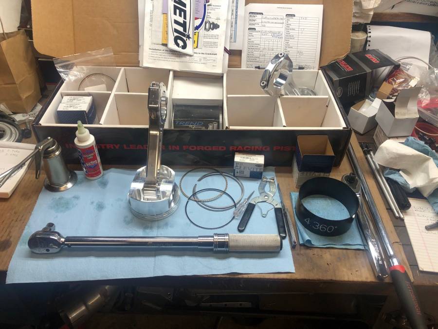
I’ve never used these 3,3,9mm rings before, wow are they thin and delicate… I put the oil rings on just to hold the piston in the hole and I’m going to have to be really careful when installing because it’s going to be very easy to roll one of the oil ring when installed and I’m not sure I would know until after the motor was together…
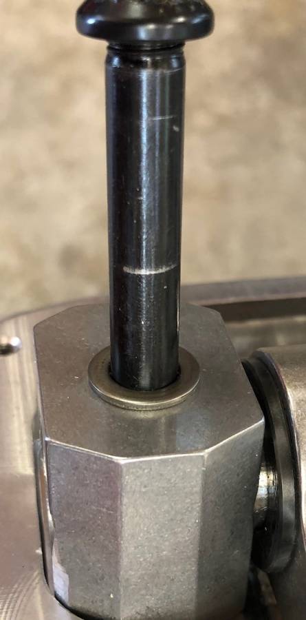
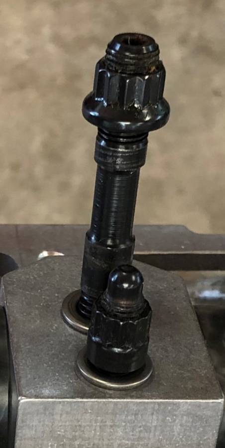
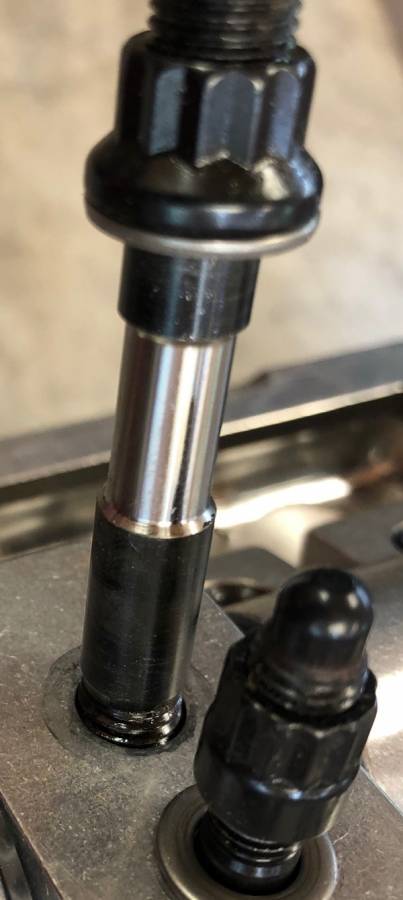
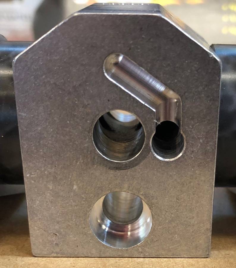
Here are a few pictures of the T&D 1.7 rockers. I went with the single shaft rather than the paired rockers. Koffel assured me they would hold up and it would save a little $ and enable me to use standard through the block oiling.
As you can see the studs are machined down to allow the oil to travel through the shafts and you can see on the bottom of the hold down block where it’s been machined to accept the oil from the block oil passage and then feed the shaft which will feed the rockers and push rod cups. I will put .060 restrictors in the head to control the oil (I’m also dropping the cam off to the machine shop to have the groove the #4 journal for full time oiling to the heads/rocker)
The lifter bore on the KB block are .905 and the BAM lifters are .904 so they are on the tight side. I test fitted the lifters in each of the bore and you have to be perfectly straight to get them to go in and a couple of them are a little snug. I’m thinking that will be ok as the aluminum will grow with heat but I’m going to discuss it with my machinist to make sure he’s in agreement.
Also dropping off the rotating assembly to be balanced. Once that is done, I should be able to put the motor together, hoping to make some races in July (NHRA SST double divisional at Topeka is my goal)
Ordering MT front runners and slick this week as well as the APD Max Speed carb (ouch $).
The tranny was fine but it had a ton of passes on the 1.80 straight cut gears so I picked up a new set and it's getting put together so the tranny will be fresh and ready to go.
I also put a new set of Richmond 4.56 Pro gears in the Dana 60. Nothing wrong with them but they had 10 years on them so preventative maintenance.
Posted By: Al_Alguire
Re: 508” KB – B1 build - 06/01/20 04:45 PM
Wade we ran common shaft T&D's ont he B1 in the dragster, not because I wanted to but KB screwed up the block(was to bu pushrod oil and 55MM, they did non rushrod and 54) so we had no choice. Never had an issue with anything in the valvetrain that way. Engine made 1020 and went 7.30's here in Vegas in the Racetech. I would nto worry much about the rockers..AS for clearance yeah you got a TON of room

Posted By: markz528
Re: 508” KB – B1 build - 06/03/20 01:53 AM
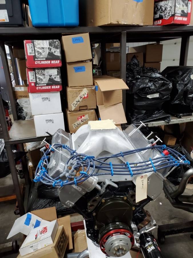
Tony Bischoff (BES) did a great job on my intake. They cut the flanges off and welded new ones. You can't tell. And everything is o ringed including the valley pan.
Posted By: 440Jim
Re: 508” KB – B1 build - 06/03/20 03:37 PM
Tony Bischoff (BES) did a great job on my intake. They cut the flanges off and welded new ones. You can't tell. And everything is o ringed including the valley pan.
O-rings for the intake ports will be nice.
What is the port opening dimensions on your setup? 2.70" x 1.65" ish?
Posted By: WadeMetzinger
Re: 508” KB – B1 build - 06/03/20 03:43 PM
Question for you guys that have build KB and B1 motors, did you helicoil any of the threads in the heads or the block?
Posted By: markz528
Re: 508” KB – B1 build - 06/03/20 04:11 PM
Tony Bischoff (BES) did a great job on my intake. They cut the flanges off and welded new ones. You can't tell. And everything is o ringed including the valley pan.
O-rings for the intake ports will be nice.
What is the port opening dimensions on your setup? 2.70" x 1.65" ish?
Don't know..........
Posted By: Al_Alguire
Re: 508” KB – B1 build - 06/03/20 04:12 PM
Question for you guys that have build KB and B1 motors, did you helicoil any of the threads in the heads or the block?
No. The one thing to watch is adequate thread engagement into the block for sure. As for the heads unless they are REALLY old should be no need.
Just had the small port(282cc)B1 heads on the dyno yesterday made good power for a tiny port. 937@6900
Posted By: WadeMetzinger
Re: 508” KB – B1 build - 06/04/20 02:48 PM
Thanks Al for the response and others as well!
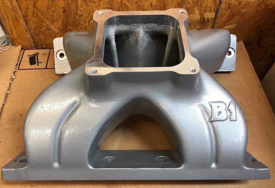
Intake, valve covers and Indy 2 piece valley tray power coated.
Heads were milled .040, oil passage in head tapped for 10/32 set screw that will be drilled .060 to restrict oil going to the heads. (need to mock up the heads and intake to see how much if and how much the intake needs to be milled)
Compression should be 12.46:1 after milling the head and getting the head chambers down to 64cc
#4 journal on the cam grooved for full time oiling
Rotating assembly balanced. (he took a lot of the weight off counter weights in the lathe but still had to drill a lot of holes)
-2007 gram bob weight!
o 2.100” rod journal as opposed to 2.200”, lighter rod and rod bearings
o 4.360” bore as opposed to 4.5”, smaller and lighter piston
o 3, 3, 9mm rings as opposed to 1/6, 1/6, 3/16 or .043, .043, 3/16
It’s setup for spin high rpms but I’m hoping to keep it well under 7,500. Shift at 7,200, I probably wouldn’t be able to do that if I would have had the heads fully ported.

Posted By: WadeMetzinger
Re: 508” KB – B1 build - 06/04/20 04:21 PM
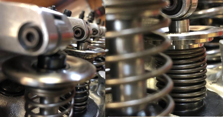
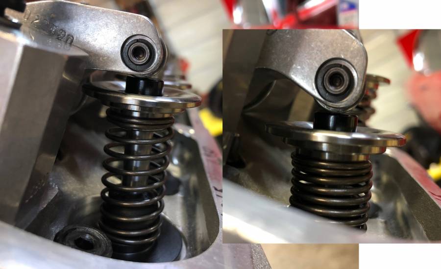
How about some help with where to install the valve springs:
Springs:
PSI DR426RML
1.500"
300Lbs seat at 2.050”
840lbs open at 1.150
Rate 600
Cool bind 1.100
Cam:
.767/.767 276/288 110 lob sep 108 centerline
With them installed at 2.050 they will be .183 from coil bind and I think you want to be closer to .050 from coil bind correct?
But if I install at 1.917 (2.050 - .133 (.183-.050)) that will give me 380lbs seat and 940lbs open pressure and that sounds like too much, thoughts?
Posted By: Cab_Burge
Re: 508” KB – B1 build - 06/04/20 05:41 PM
Some internet "guru" will tell you that they like .055, some will say .100 from coil bind. I use what the spring makers suggest

Keep in mind, especially with aluminum heads that the head will grow taller as it warms up and the valves won't grow as much so the clearances on coil bind will be less with the motor warm up so I shoot for .060 to .080 from coil bind at room temps on all 16 springs on aluminum heads


Posted By: Al_Alguire
Re: 508” KB – B1 build - 06/04/20 09:53 PM
I would tend to agree with Cab and using the manufacturers recommendations for sure, especially when using nee pieces. I don't think you will need to see near the RPM you think you will. Have done a bunch of b1 stuff over the years and with those kinda cam specs id be willing to bet peak is closer to 7000-7200
Posted By: WadeMetzinger
Re: 508” KB – B1 build - 06/05/20 10:28 AM
Thanks for you.re input guys!
Posted By: WadeMetzinger
Re: 508” KB – B1 build - 06/09/20 01:54 PM
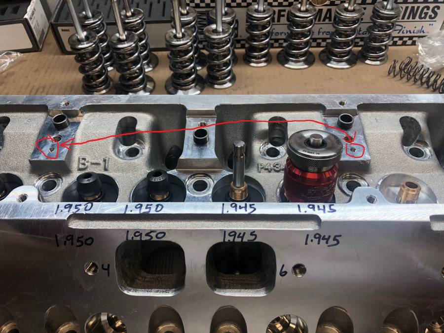
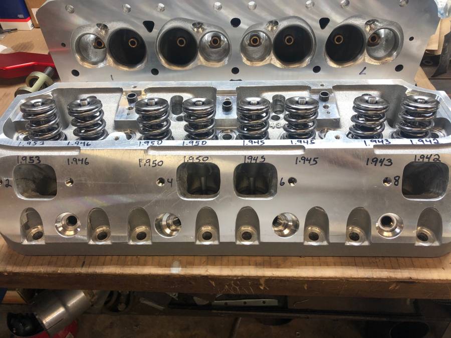
I got the valve springs setup on the heads. They set up from 1.940 to 1.950 so that's between .073 and .083 from coil bind. (using the valve seals to hold the shims and locators in place until final assymbly)
Before I install the PSI springs, I will put on the 8 checking springs and make sure I have push rod clearance in the head and the block.
I drilled the 10/32 set screw to .060 to restrict the oil to the heads (I circled the 2 10/32 taped oil passages in the heads)
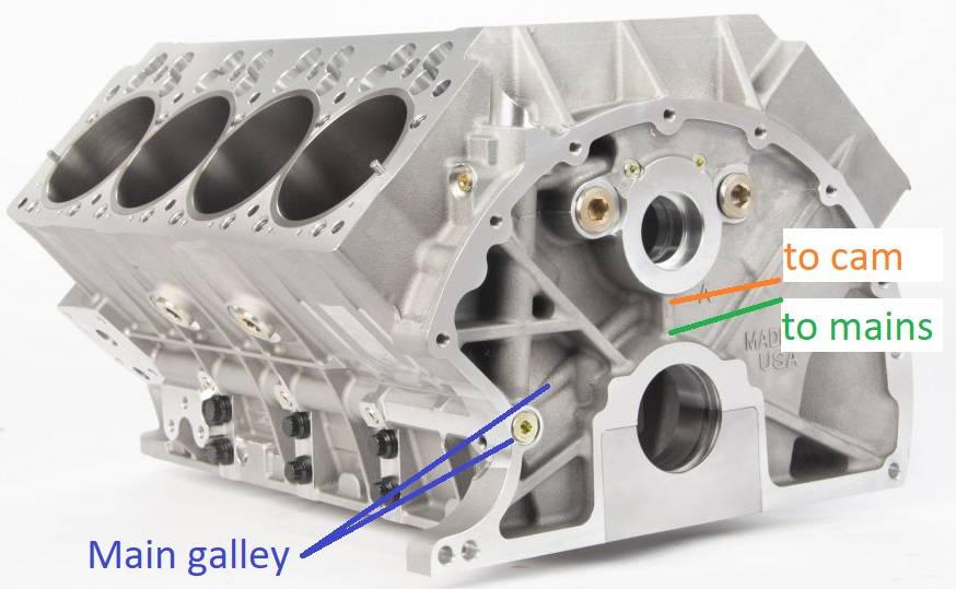
I chased the oil passages with one of those flexible small diameter lights to see where they went and make sure there weren't any obstructed and noticed that KB put restrictors in the oil passages from the mains to the cam journals. The restrictors were around .080 and since I'm oiling the heads via the #4 journal that are 2 .060 felt I needed to open that one up some so I got a long drill bit and drilled the #4 restrictor out to .180
Posted By: 440Jim
Re: 508” KB – B1 build - 06/09/20 03:08 PM
It is my understanding that those oil restrictors above the mains are part of the "priority main" oiling system. So if you loose pressure to the cam or lifters; the mains still have some oil pressure to make it live until engine is shutoff. It can change the running oil pressure measurement in the lifter bores & cam bearings compared to the mains. I was pushrod oiling my KB motor, and the pressure in the lifter galley was just right so I didn't need to restrict oil flow to the heads.
Posted By: WadeMetzinger
Re: 508” KB – B1 build - 06/09/20 04:11 PM
Jim, that makes sense so by drilling this out from .080 to .180 (rechecked the sizes) it will reduce the oil pressure to #4 main compared to the others in the even of pressure/volume loss from top end. Hopefully that doesn't happen and if it does hopefully the coated main bearings will buy me a little more time/safety.
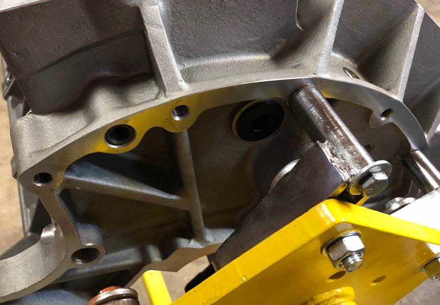
Here are picture of the drilled out oil restrictor on the bottom of #4 cam journal and then un-touched #3 cam bearing journal (a little blurry)
That KB picture you posed must be the newer and redesigned blocks as mine doesn't have that port on the back left side (around 10 o'clock)


Posted By: WadeMetzinger
Re: 508” KB – B1 build - 06/09/20 04:11 PM
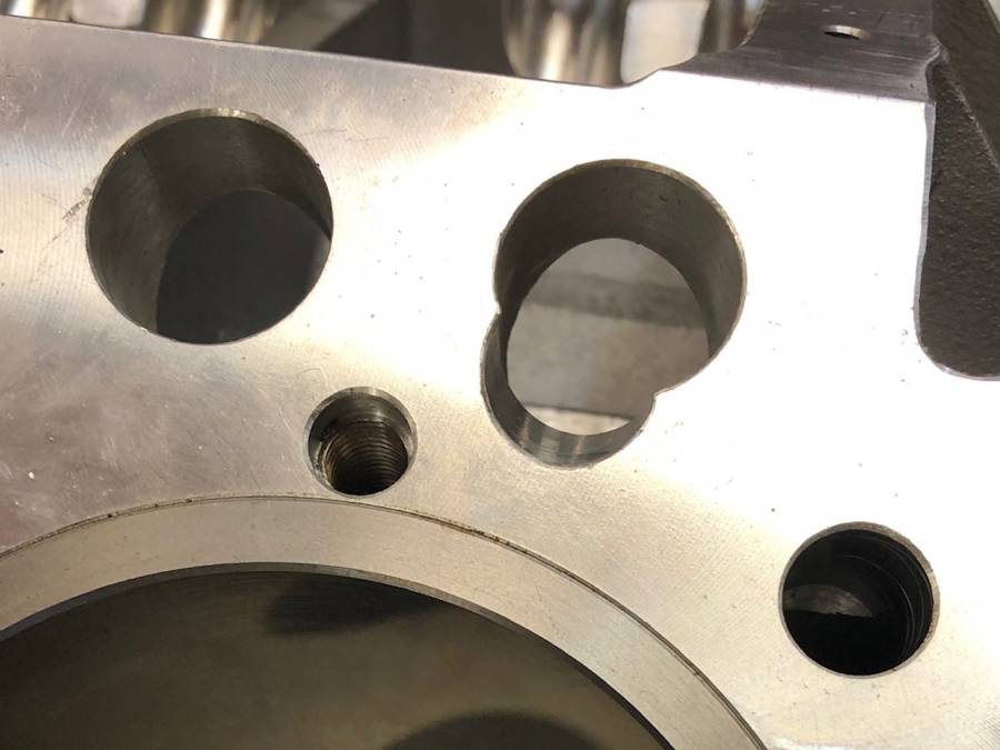
Here is a picture of my pushrod opening on my KB block, when I was checking Piston to Valve clearance, there wasn't any interferance but I know you had to do some clearancing, wonder if that was because it was a low deck or the pushrod angle on the -1 heads...
Posted By: WadeMetzinger
Re: 508” KB – B1 build - 06/14/20 01:57 PM
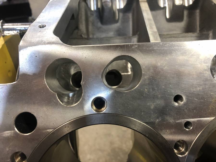
The checking pushrods didn’t appear to make contact but They are 3/8 and I plan to use 7/16 on the exhaust so I marked the block where it didn’t match up with the openings on the heads and opened those up.
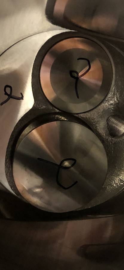
I also turned the block over and checked it see if the valves got close to the cylinder walls since it’s on a small bore but as you can see in the pic with the valve fully open they weren’t even close.
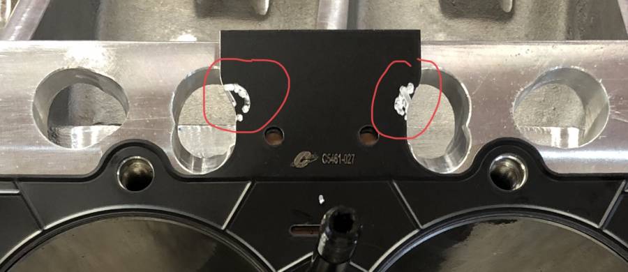
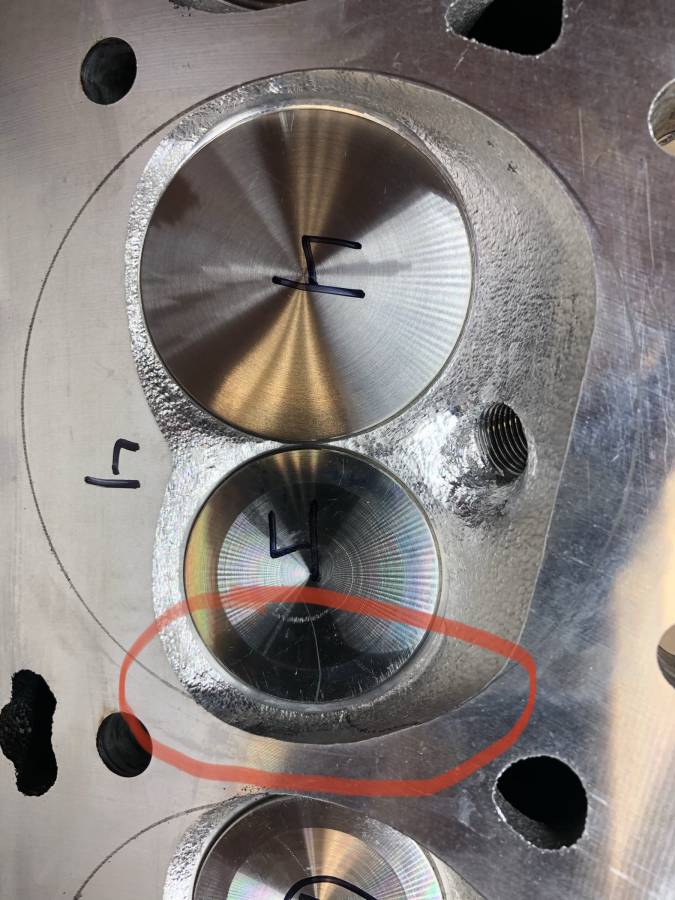
I then traced the cylinder bore with a pencil on the heads. The only concern is between number 1,3 and 2,4 cylinders, as the chamber is right on line. Since I’m using a 4.380 head gasket it should be fine but I need to look how the gasket sits on the head to be sure.

Posted By: WadeMetzinger
Re: 508” KB – B1 build - 06/14/20 02:00 PM
Bore traced on head
Posted By: Cab_Burge
Re: 508” KB – B1 build - 06/15/20 02:29 AM
Posted By: 440Jim
Re: 508” KB – B1 build - 06/15/20 01:53 PM
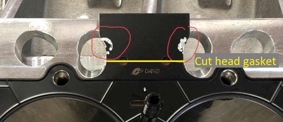
Cab, I have done the same. Cutting off where I put the yellow line.
Posted By: Al_Alguire
Re: 508” KB – B1 build - 06/15/20 05:41 PM
Cut those tabs off..Also we make room for the rivets in the Cometics as the B1 heads are kinda big on those spots. Is it necessary no, but makes it look better

![[Linked Image]](https://i.postimg.cc/TYtRpBDm/785-CA943-0-F44-41-F7-BDC4-E7673-AAC0466.jpg)
Posted By: WadeMetzinger
Re: 508” KB – B1 build - 06/15/20 06:48 PM
Al, That's much prettier than my rat tail filing I did to make room for the rivet.
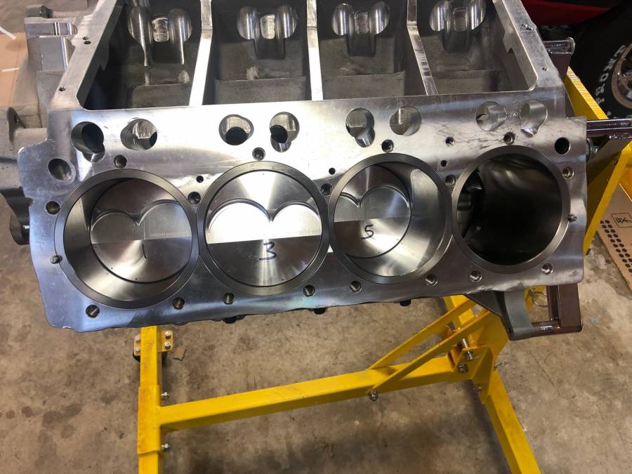
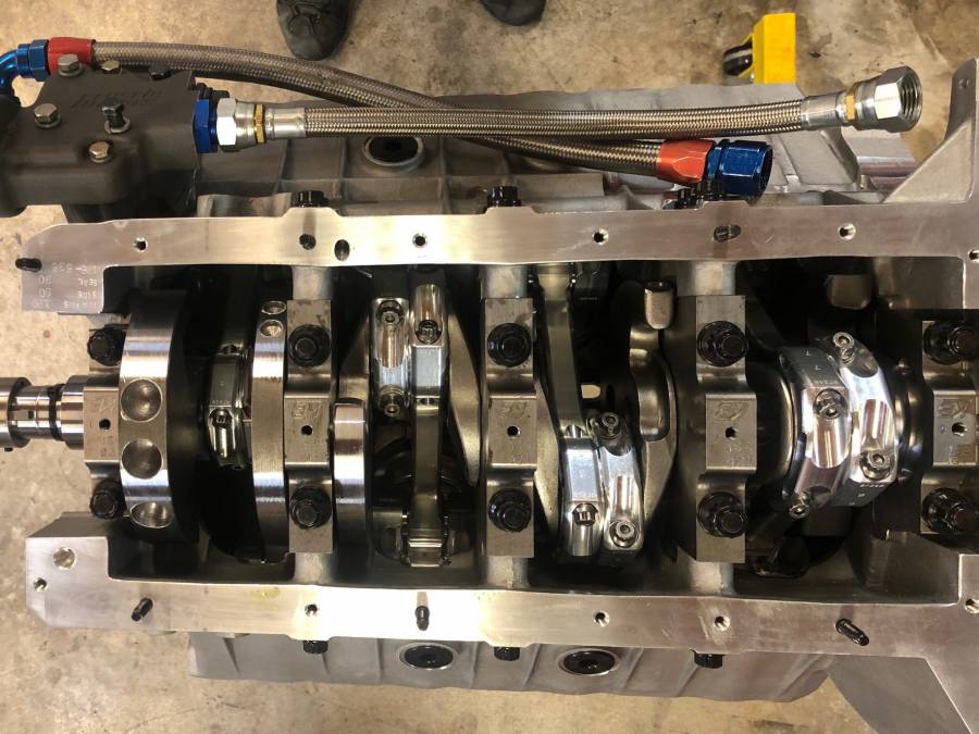
I got 6 of the pistons installed over the weekend, I was really nervous about rolling an oil ring since they are so small but so far so good (I probably just jinxed myself).
.026 ring gap on both top and bottom rings per Total Seal, I think I had 2 end up being closer to .028-.029... oops
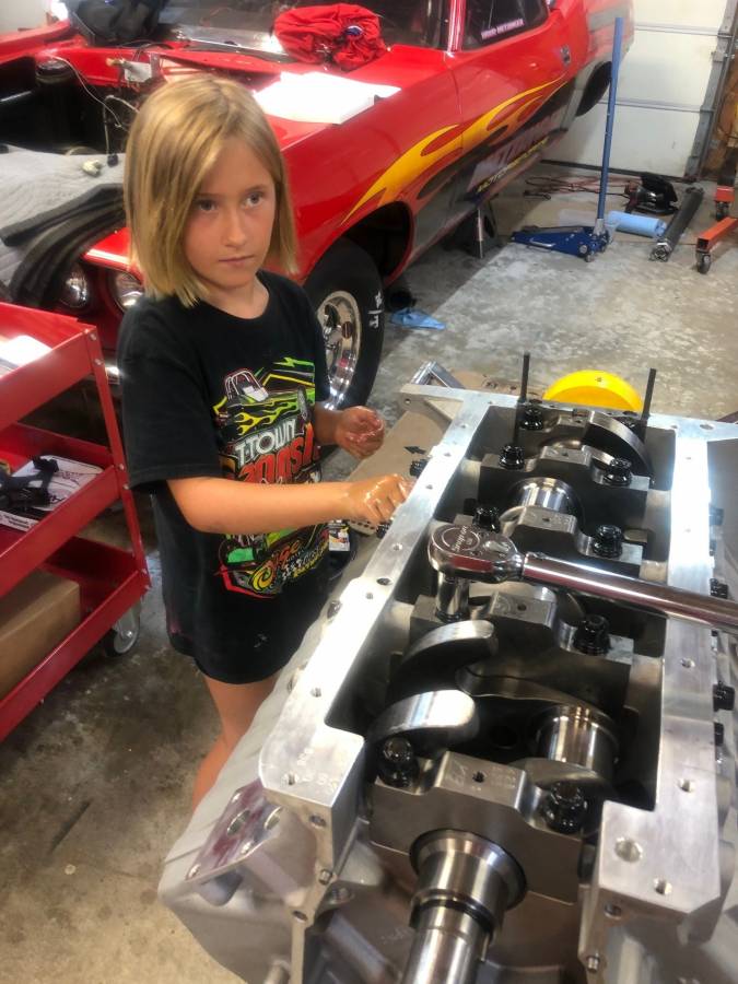
The main and rod called for just oil on the threads so it wasn't as messy as other motors.
The washer on the rod bolts is like 1/4" thick and didn't seem removable, so that was different, just had to take out the bolt, clean it, oil it and then install and torque it in 1 single motion to 75lbs. I didn't check the bolt stretch, they were just ARP2000 bolts. But I do use the bolt stretch method with using the custom age 625 bolts.
That was my first time to install the "dog bone" rear main seal, it was interesting but I think it's a good design.
There was a lot to torque on the block with the dual side bolts and the mains being 5/8". Man 120lbs torque was a work out, I could have used a longer torque wrench. (my daughter helped me oil all the threads and washers, she said she like all the oil on her hands and said if we could make a pool full of oil so she could swim in it and I proceeded to tell her that they do have oil wrestling evens to which she asked to go participate in... I left out the barely clothed women part)
Rod clearance was between .0028 - .0030
Main clearance was between .0029 - .0033
Here is how I check the clearance:
1. I checked the clearance by mic'ing the crank, locking the mic, recheck the crank and then put it in a soft jaw vice.
2. I then take a dial bore gauge and measure the main journal with the bearing and torqued at 12 and 6 position, and find the smallest measurement and Zero out the gauge and then recheck.
3. Then I take the dial bore gauge and measure the center of the mic pads that is held by the vice.
I have repeated this for all the main before but typically if it's in the .0025 - .003 range, I will just set the crank in dry and plasigauge the rest of the mains.
How do you guys check rod and main clearances?
.025 side clearance on the rods, still need to check the crank thrust clearance.
I feel like it's all down hill from here...
Posted By: sasquatch
Re: 508” KB – B1 build - 06/15/20 07:38 PM
Hey
Go move that jack handle for me.......Way to close to pretty paint for my old heart to take.......Looks pretty good so far.
Todd
Posted By: markz528
Re: 508” KB – B1 build - 06/15/20 08:48 PM
It looks might purty and I am jealous of your help!
Posted By: Cab_Burge
Re: 508” KB – B1 build - 06/16/20 02:41 AM
Throw the plastigauge away

It was a old tool for farmers and your regular automotive garage mechanixs, no place for it in in Hi Po engine building

Posted By: WadeMetzinger
Re: 508” KB – B1 build - 06/30/20 06:28 PM
Not much progress to report (I spent the last week racing Jr dragsters with my daughter at the NHRA Western Conference Finals) but I did finish the bottom end, springs set up on the heads and checking for #8 bung placement for oil drain back lines from the heads.
I have a new Milodon oil pump and Muscle motors cover for this motor but I think I'm just going to reuse the one I had on the 540" Frankenstein motor since it was working just fine and already set up. (I did pick up a new 4.25" stroke crank and 7.100" pistons from Molnar through Marsh Performance to put that motor back together for a back up)
I'm not sure if the new owners of KB still do this but when I purchased mine, it came with head studs, oil pan stud and timing cover studs, which was really nice.
-
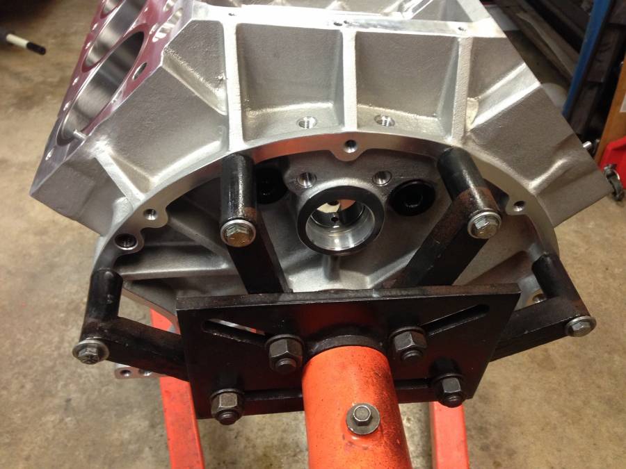
Anyone know of a kit or where to pick up bell housing studs? Since it's an aluminum block, I'd rather put studs in the block to mount the tranny too (J&W Ultrabell) rather than using 3/8 bolts.
I found these on ARP's site, but they are for Top Fuel and 7/16 but didn't see any in 3/8 size:
APR bell housing studs
Posted By: rickraw
Re: 508” KB – B1 build - 06/30/20 07:53 PM
Everything looks real nice. I made my own studs from hardened all thread. Worked fine.
Posted By: WadeMetzinger
Re: 508” KB – B1 build - 06/30/20 08:09 PM
Everything looks real nice. I made my own studs from hardened all thread. Worked fine.
I'll do that if I can't find any but I like how APR studs have that necked down non-thread ends to help as you get them aligned.
Posted By: 340Cuda
Re: 508” KB – B1 build - 07/01/20 01:59 PM
Wade,
If you know the length of the studs you want you can call or email ARP and they will tell you if they have them.
Summit's search engine filters also work pretty well when looking for studs.
Bill
Posted By: 440Jim
Re: 508” KB – B1 build - 07/01/20 07:33 PM
Anyone know of a kit or where to pick up bell housing studs? Since it's an aluminum block, I'd rather put studs in the block to mount the tranny too (J&W Ultrabell) rather than using 3/8 bolts.
I found these on ARP's site, but they are for Top Fuel and 7/16 but didn't see any in 3/8 size:
APR bell housing studs Will this ARP kit work for you?
Kit #: 245-0901 Stud Kit - Chevrolet, Chrysler KB Hemi, hex
Specifications
OAL 2.000˝
Thread Size 3/8˝
Nuts, washers included Socket Size(s) 7/16 12pt
Summit LinkAlso available in stainless steel 445-0901
Posted By: 440Jim
Re: 508” KB – B1 build - 07/01/20 07:45 PM
Another alternative:
Summit Racing Part Number:MIL-81520
Fastener Head Style:Flanged 12-point
Stud Length (in):2.000 in.
Thread Size:3/8-16 in.
Fastener Material:Chromoly
Fastener Finish:Black oxide
Quantity: Sold as a set of 6.
Summit Link - Milodon
Posted By: WadeMetzinger
Re: 508” KB – B1 build - 07/01/20 08:23 PM
Awesome Jim, I think that will work! Not sure why that kit didn't pull up on APR's site..
Posted By: 440Jim
Re: 508” KB – B1 build - 07/01/20 08:36 PM
Also found some lower cost alternatives, Summit says they are grade 8.
Dorman 675-004
2.125" OAL $13.99 set of 10
Double Ended Stud - 3/8-16 x 5/8 In. and 3/8-16 x 1 In, with 1/2" unthreaded
Link to Dorman web site 675-004These might be more to your liking (if not paying for the nice ARP)
unthreaded tip
Summit Link Dorman 675-115
Posted By: sasquatch
Re: 508” KB – B1 build - 07/01/20 09:05 PM
thanks jim. You just saved me the trouble of looking that up. For future knowledge the ARP specials dept is 805-525-1497. Sam Benson is the guy to ask for if he is still there. They have tons of stuff not in the catalogs if you ask the right person.
Todd
Posted By: WadeMetzinger
Re: 508” KB – B1 build - 07/06/20 03:34 PM
This weekend I got the cam installed and degreed in at 108.5 with Jessel belt system, .011 end play.
I got the heads installed and checked rocker arm geometry and measured for pushrods. Intake 3/8" diameter .120 wall and 9.704 over all length, ball to ball, 5/16 ball ends, Exhaust 7/6" diameter .095 wall and 9.671 over all length with 5/16 ball to ball ends. This was with .006 lash accounting for .010 - .015 growth for aluminum block and heads.
I also noticed that the side spacing on the T&D rockers weren't the same so I measured them. They varied from .014 to .065 so I've got a call into them to find out what space they recommend so I can adjust with shims. I'm guessing they will want .020 or less. The .065 will let a lot of oil out and may starve #1 since it's so far away from the supply.
I set the intake and spacers on to see how they aligned since we milled .040 off the head to increase compression. They seemed to still align pretty good but i did order some .030 intake gaskets to see if they will help align even better.
Also took measurements of the valley tray bolt and the intake bolts so I could get them ordered. 1/4x20 at 3/4" length for valley tray and 3/8x16 at 2.5" length for intake bolts.
The tranny studs came in and they look like they are going to work nicely, i didn't realize the KB blocks had both Chevy and Mopar bolt patterns, that will offer a few other options.
Next I'm going to figure out where to have the #8 oil drain back fittings welded to the oil pan, i'm running the Milodon 31161 9QT pan chassis/dragster pan with the dual line swinging pick up and there isn't a lot of room for the fitting above the oil level and the windage tray so I'm stressing a little about that at the moment.
Hoping to be ready for the dyno in the next 2 weeks. I'm hoping for 900hp but realistically expecting 850-875hp.

Posted By: WadeMetzinger
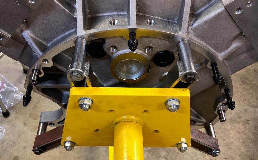
Re: 508” KB – B1 build - 07/06/20 03:39 PM
Pic of the tranny studs, they aren't in the right hole, just checking fitness, also screwed in the ARP dowel pins
Posted By: 440Jim
Re: 508” KB – B1 build - 07/06/20 04:33 PM
Pic of the tranny studs, they aren't in the right hole, just checking fitness, also screwed in the ARP dowel pins
Let us know if the tranny studs are long enough. I think you are using a JW Ultra bell (thick) and a mid-plate?
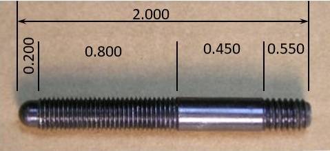
And can you tell me the coarse thread length, fine thread length, quick start end length. Catalog says 2.0" overall length.
Posted By: 440Jim
Re: 508” KB – B1 build - 07/06/20 05:40 PM
ARP replied to my online inquiry quickly. This is their reply:
Hi Jim,
Thanks for the inquiry.
.200” nose
.550” coarse
.800” fine
So this picture is my interpretation of that, assuming exactly 2.0" overall length. (pic is a different stud).
Posted By: WadeMetzinger
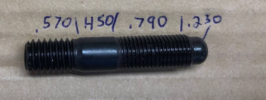
Re: 508” KB – B1 build - 07/06/20 07:00 PM
My picture isn't as pretty as yours is but here is a pic with the measurements I took with dial calipers. I included the tapering up to the flat spoton the course side since it will engage into the block that far.
Posted By: 440Jim
Re: 508” KB – B1 build - 07/06/20 10:33 PM
That agrees within est of thread start/stop.
I worry it will be close with a midplate (0.25") and JW bell (0.75"?)
Posted By: WadeMetzinger
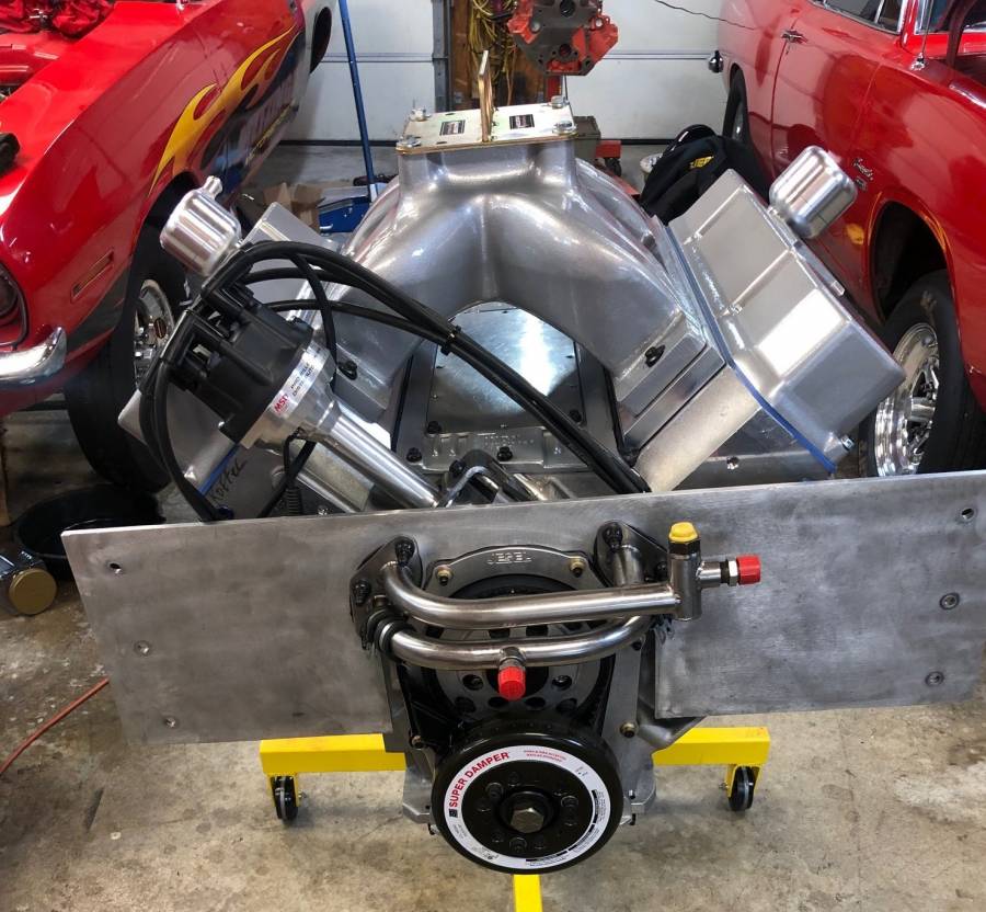
Re: 508” KB – B1 build - 07/13/20 05:22 PM
Installed the lifters, pushrods, rockers and adjusted the valve to .006.(assuming they will grow .010 to .015 when hot)
Installed the intake and spacers, since I milled .040 off the heads I swapped out 1 set of the .060 gaskets with a set of .030 and everything lined up perfectly.
Installed the oil pump drive and checked engagement of the distributor shaft and test fitted the Milodon oil pump and Muscle Motor pump cover.
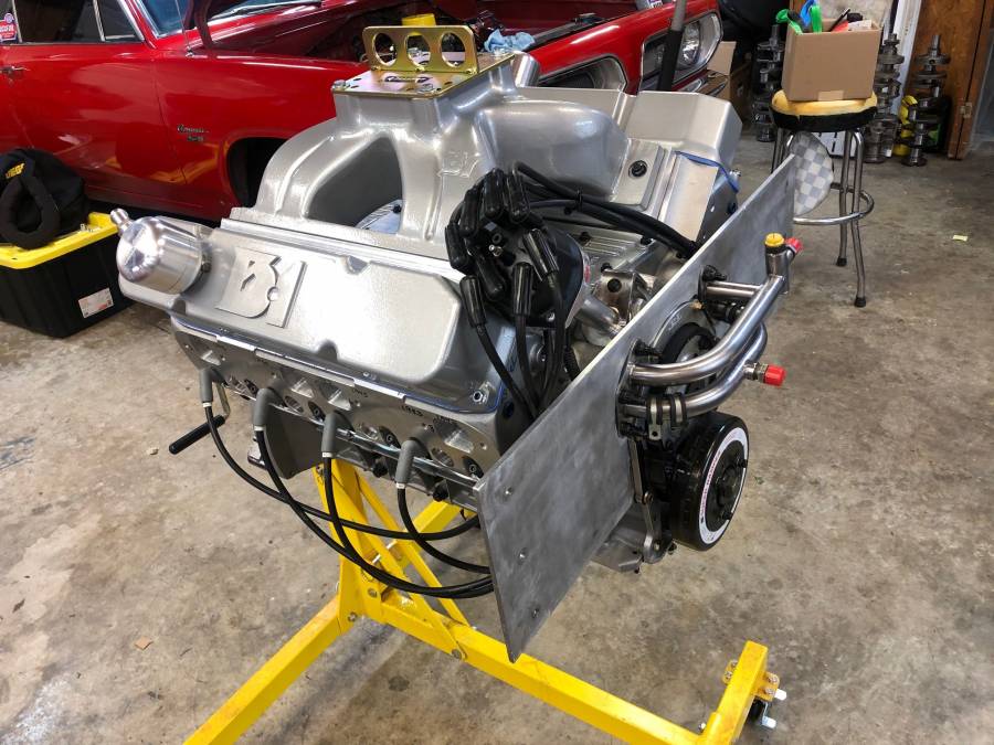
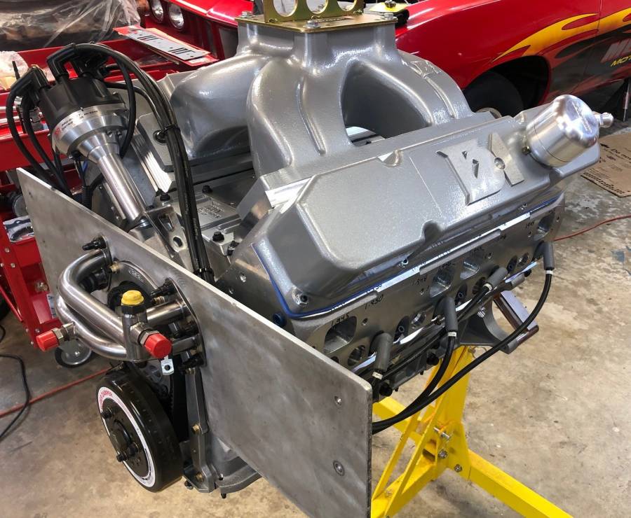
Cut holes in the valve covers for the evac breathers and also installed baffles. No room for a vacuum pump so have to keep using old school evac system through the headers. (Alternator and Enderle fuel pump take up all the room up front)
Installed new cap and rotor and set up the wires (also swapped #4 and #7 for the cam).
Oil pan is getting 2 #8 bungs welded onto it for oil drain back from the heads, should be ready this week so I can pre-oil it.
APD 1275 Max Speed gas carb should be in the mail this week, will be using Renegade 112 race fuel.
I was hoping to dyno this week but it looks like it will be the week after the Topeka NHRA double divisional. A buddy of mine is letting me wheel his 1967 Camaro in SST. It's a beautiful all steel, all glass car that has been in their family for 50 years. Big Block Chevy 582” makes around 1,100hp but the car weighs a ton, like 3,400+ lbs.

Posted By: tex013
Re: 508” KB – B1 build - 07/13/20 09:40 PM
wow the motor looks great , camaro not so bad either
Tex
Posted By: Al_Alguire
Re: 508” KB – B1 build - 07/14/20 02:04 PM
Looking good..Id try really hard to find a home for a vacuum pump myself. I know things can get tight but gotta be a way. We have a dry sump, vac pump and alternator hanging on mine with extremely narrow frame rails. Tight but it all works.
Nice Camaro, I to have a 68 Camaro with an BBC in it that I have threatened to run in S/ST more than once. It is a true street car though and just have never bothered to put a diaper on it.
Posted By: WadeMetzinger
Re: 508” KB – B1 build - 07/21/20 04:00 PM
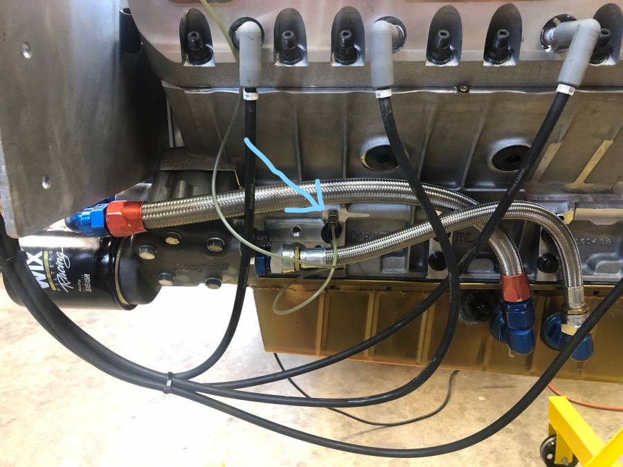
Got the oil pan on and routed the oil lines.
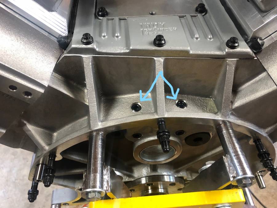
Pre-oiled the motor and took oil pressure readings from 2 different places, 1 from the back top/bellhousing area and then from the side, the main oil galley. 440Jim did this as well and told me that the back top oil pressure was down because how it was restricted as that oil is after all the mains are oiled and they the oil goes to the outside of #5 cam bearing and and then to the back top port which is also when/where the lifter oil galley is supplied (the cam bearings are oiled from the mains so they are 2nd in line after the mains.
I use an old corded 1/2" drill that only spins at 900rpm and got 50lbs on the top back port and 75lbs on the side main galley port.
I then switched to my Milwaukee cordless which spins around 1,800rpm and it immediately pegged my 80psi oil pressure gauge. (I haven't check the top oil port with the faster drill yet)
I didn't use the lifter galley oil restrictors per 440Jims recommendation and it looks to be a good decision.
Now just waiting on the Carb and shooting for Dyno Friday, JULY 31st.
Anyone want to make any HP/TQ predictions?
Posted By: 440Jim
Re: 508” KB – B1 build - 07/21/20 06:29 PM
I use an old corded 1/2" drill that only spins at 900rpm and got 50lbs on the top back port and 75lbs on the side main galley port.
I then switched to my Milwaukee cordless which spins around 1,800rpm and it immediately pegged my 80psi oil pressure gauge. (I haven't check the top oil port with the faster drill yet)
I didn't use the lifter galley oil restrictors per 440Jims recommendation and it looks to be a good decision.
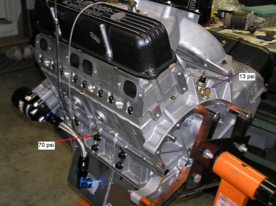
I think KB didn't machine the groove around the cam bearing deep enough on mine. Ken said he was surprised by my oil pressure (with the slow drill); 70 psi mains, and only 13 at the lifter galley. But the oil flow to my heads (via pushrods) was enough as I watched it on the engine stand. Engine worked great (only pushrod oiling to the Indy 440-1 heads, T&D paired rockers).
Posted By: 440Jim
Re: 508” KB – B1 build - 07/22/20 12:21 PM
Anyone want to make any HP/TQ predictions?
Time for the guessing game!
Sounds fairly mild for a B1 build:
508 CID (4.360” x 4.25” stroke), 12.46 CR,
392 cfm Koffel porting, 276/288 deg at 0.050", 0.767”/0.767” camI hope it makes more, but I am guessing 958 hp at 7200 rpm. (rpm due to only 508 CID)
Posted By: Al_Alguire
Re: 508” KB – B1 build - 07/22/20 02:02 PM
The bore size and compression IMO will hurt more than anything else. Id bet its closer to 900, but hope I'm wrong. And all dynos are different more intersted to see the MPH in the car.
Posted By: LA360
Re: 508” KB – B1 build - 07/23/20 02:35 AM
Why are the later cast B1 valve covers taller than the early ones? Does anyone know. The early ones are about 2.5" tall
Posted By: markz528
Re: 508” KB – B1 build - 07/23/20 03:42 AM
I'm gonna go with 930 hp............
Posted By: Al_Alguire
Re: 508” KB – B1 build - 07/28/20 02:56 PM
Why are the later cast B1 valve covers taller than the early ones? Does anyone know. The early ones are about 2.5" tall
Because they are cast by Indy. Same cover with a different logo on top, beneficial for both companies.
Posted By: WadeMetzinger
Re: 508” KB – B1 build - 07/28/20 07:24 PM
I'm thinking 875 to 900 so I'll say 885 but will be really happy with 900.
Posted By: HardcoreB
Re: 508” KB – B1 build - 07/30/20 12:11 PM
Nice handywork Wade! Good luck on dyno I'm with you 900ish.
Posted By: WadeMetzinger
Re: 508” KB – B1 build - 08/01/20 02:57 PM
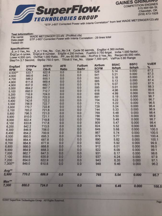
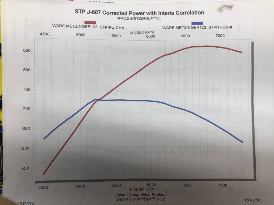
866hp at 6,800 and 724tq at 5,200
700tq from 5,000 to 6,500
1.7 hp per cubic inch
I was hoping for a little more but knew 850 was more realistic Small cid 508”, lower compression 12.4 and stage 1 ported heads so there more power to be had but I think this will be perfect for what I’m doing. Definitely not working the components any where near their limits.
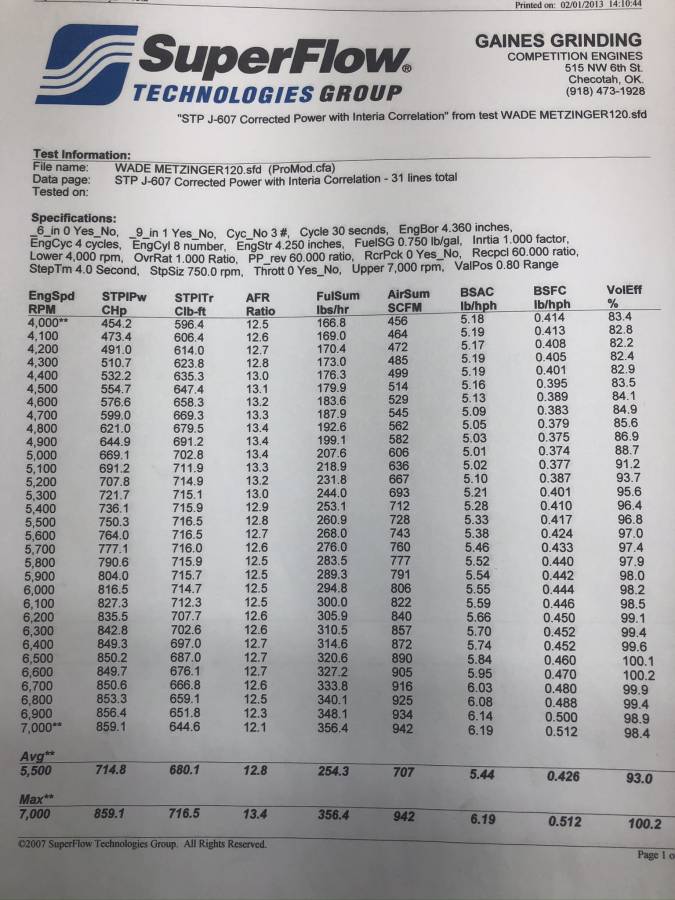
1st two pictures were the final pull using my mechanical pump and the 2nd was the final pull using the Dyno fuel syste, it was still Miami good power at 700 but was lower, it was only at 5.7psi fuel pressure and mechanical was lower to 6.5.
I’ll post picture of the air fuel oil pressure and fuel pressure later, I left without those so getting them sent.
Posted By: 440Jim
Re: 508” KB – B1 build - 08/01/20 09:13 PM
Every dyno is different, so the number is just a number. Was that with the gasoline carb?
I am surprised it peaked at such "low" rpm; both the torque (5,200) and the horsepower (6,800).
I was expecting around 5,500 and 7,200 rpm.
And using the Dyno fuel system the peaks were 5,600 and 7,000+ ??

They are good numbers for sure, but I’d like to hear how the dyno fuel system was hooked up to the motor.
Were the fuel lines coming from the dyno and going directly to the carb?
For the run using the dyno fuel system, the BSFC numbers don’t really make a lot of sense.
Primarily, in that the weather correction factor(based on what the BSFC numbers work out to for uncorrected HP) appear to change from about 12% at the start of the pull....... to about 19% at the end of the pull.
Based on the fuel flow and BSFC number for last line of that sheet, the uncorrected HP should be 696HP.
Posted By: WadeMetzinger
Re: 508” KB – B1 build - 08/03/20 04:22 PM
This was using gas (Renegade 112), first time in 20 years I'm running gas. All the .90 index say that you can predict day to day changes much easier with gas over alcohol. They did say if you could always get a time trial before eliminations that alcohol is the way to go but NHRA .90 racing doesn't work they way most of the time. (was told this by APD and several very successful .90 racers)
The dyno fuel system was an Aeromotive A2000 pump to an Aeromotive 2 port dead head regulator. He builds and dynos a lot of big hp motors and it works fine. I thought he run a little low on the pressure, on those pulls it ran from 4.8 - 4.4psi.
For my fuel system, I'm using my 20+ year old Enderle mechanical pump (it's been rebuilt and tested several time) and spring/shim bypass regulator you can see just on top of the pump. For Alcohol I've just ran that and didn't run another regulator so it idled at 3psi and went up to 9 psi down track. So we put the bigger spring and shims in it to keep at least 10psi going to the dead head regulator even at idle.
We set my regulator around 6 psi. I would have like to set it closer to 7.5 but I was in the dyno room adjusting and he was at the console telling me when it was good and we didn't discuss what psi to set it at, he just gave me the thumbs up at 6psi. As you can see in the detail sheet, it started at 5.8 and dropped to 5.4 so I'll add in another shim to the pump regulator and also increase the dead head regulator up to 7.5 psi when I head to the track.
These pictures are when we were using my fuel system using the front mounted fuel tank, the dyno fuel tanks are in the cabinet at the back of the dyno room.
Some of the challenged we faced:
- initial start up - it sneezed 2 times so we thought I had the distributor 180 out but I didn't, so we moved it 5 degree to see if that would help it
- got it started, adjusted timing to 38 degrees but it wouldn't idle below 1,600 and when it went below, it would sneeze up through the intake and die
- so we decided that some of the intakes weren't adjusted right and holding a few valves open, we re-adjusted all the valve and found a few that were too tight (I let him do it, he's quicker and had a little different method)
- also did a quick trace on some of the plug wires and 4 and 7 were swapped so good there
- started it up gain and still wouldn't idle below 1,600 so we replaced the 47 idle air bleeds all the way down to 24
- AF mixture was decent but still wouldn't idle
- pulled valve covers, plugs and wires, traced firing order and rocker motion for each cylinder and discovered that the cam wasn't a 4/7 swap cam after all......
- moved wire around, put the 47 idle air bleeds back in everything was perfect, idled down to 900 easily and AF mixture was perfect.
A one point he almost told me to take the motor home and figure out what's going on because something wasn't right and it wasn't ready for a pull....
It was good to get that figured out but now I have no idea what cam is in the motor.... the guy I got it from gave me the spec and told me it was a 4/7 swap and I confirmed with him again yesterday that it was indeed a 4/7 swap so I have no clue what cam is in the motor... I only have 1 other roller cam and it's still with my other motor.
We never adjusted the timing, we did pull the plugs a few times and they looked perfect so we didn't try moving it.
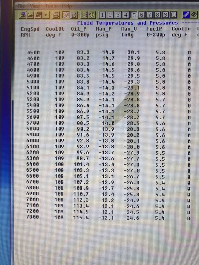
Looks like I may need to back the oil pressure down a little, but since this is pulling off the main oil galley I will probably just leave it, unless you guys think it will cause problems.
Let me know what you think about the other readings on this last chart.
One other question I had for you guys when looking at gregsdart's dyno graph compared to mine, the torque curve on mine was really flat and his was more of an arch, what would explain that and what will that mean on the track? (just curious)
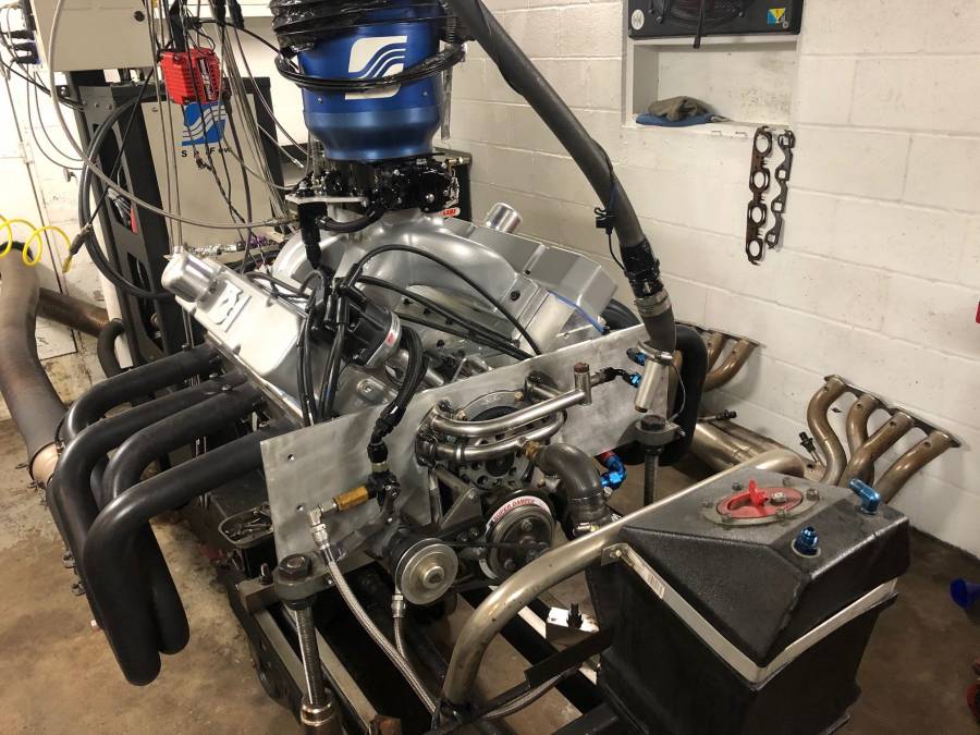
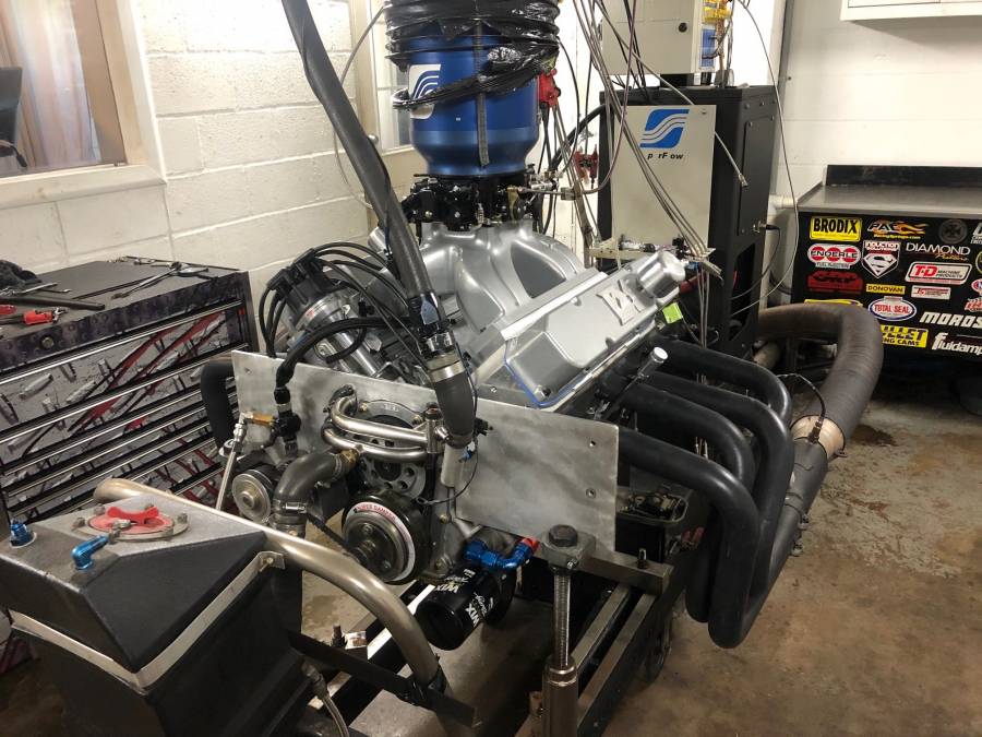
Posted By: 440Jim
Re: 508” KB – B1 build - 08/03/20 05:17 PM
Looks like I may need to back the oil pressure down a little, but since this is pulling off the main oil galley I will probably just leave it, unless you guys think it will cause problems.
The easier question...
I would back the oil pressure down some. There is no need to run anywhere near that amount (115 psi) IMO. But remember, when the oil warms up, the oil pressure will be somewhat lower.
FWIW, I would shoot for 80-90 cold at 1500 rpm (approximately). So when the oil warms up it is between 50-75 going down the track (5000-7000 rpm).
Posted By: 440Jim
Re: 508” KB – B1 build - 08/03/20 05:52 PM
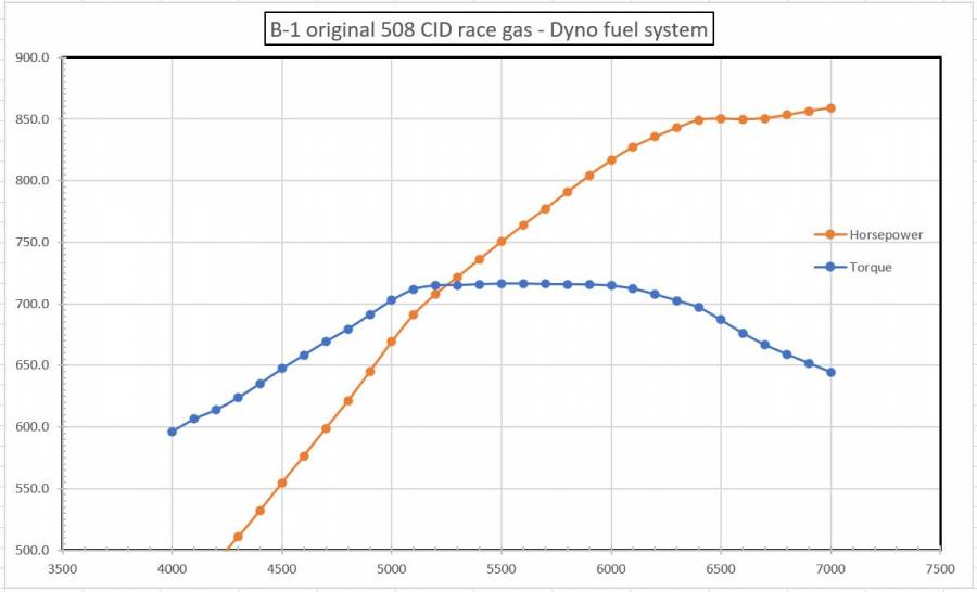
This is a graph of your data with the dyno fuel system.
I wanted to see if the torque curve shape was the same.
Is there a sheet showing the uncorrected HP from the run that has the motor running off the dyno fuel system ?
How about a sheet showing barometric pressure and air temp?
Based on what the calculated uncorrected HP should be(going by the fuel flow and BSFC numbers) the correction factor changes over 10% from the beginning of the pull to the end(12.7% CF at 4000/23.4% CF at 7000).
The correction factor is primarily used to correct for weather conditions..
A 10%+ variance is pretty big overall....... so the question is....... how can the weather inside the dyno room change that much in about 5-10 seconds?
If you look at the sheet from gregsdart the CF is within about 1% throughout the pull.
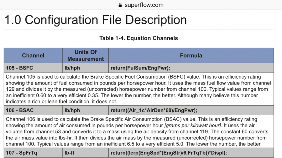
Superflow channel description and formula for BSFC:
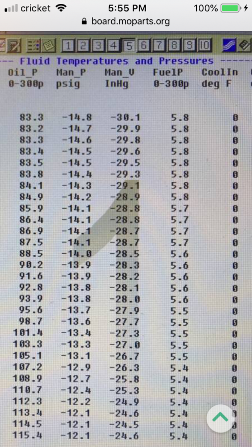
Wade...... on this page, what are the Man P and Man V measuring?
Posted By: 440Jim
Re: 508” KB – B1 build - 08/03/20 11:01 PM
if that is intake manifold pressure, it seems restricted to me. 24.9"Hg seems low, depending on what the atmospheric pressure was in the room.
Hopefully the carb was at wide open throttle.

Maybe Dwayne can give a more experienced view of that pressure (depending if it was actually the manifold pressure, and what was the room atm pressure).
Honestly Jim, I’ve never seen it expressed/displayed that way.
I’m used to seeing it as inches of vacuum.
I’m sure there is some formula to correlate the drop in pressure inside the manifold to a in/hg value.
Of course, then what is the Man V reading(displayed as in/hg)that’s showing numbers in the 28” range?
...I’m used to seeing it as inches of vacuum.
I’m sure there is some formula to correlate the drop in pressure inside the manifold to a in/hg value.
Of course, then what is the Man V reading(displayed as in/hg)that’s showing numbers in the 28” range?
Although it says psig, it looks more like manifold pressure absolute on the scale on the left. And then the in/Hg looks to be manifold
pressure rather than in Hg of vacuum, so "upside down" if you will? If those numbers are accurate from the manifold doesn't that seem like a lot of vacuum?

Posted By: 440Jim
Re: 508” KB – B1 build - 08/04/20 01:31 AM
I am simply speculating, since I have no idea what the dyno room/sensor setup is.
Man pressure could mean Manometer pressure, ie the air pressure in the room. But why was it dropping so much with engine rpm?
Really questions for the dyno operator/shop.
14.7 psi = 29.92 "Hg
12.1 psi = 24.6 "Hg
So both columns seem to be measuring the same thing.
If at low rpm (air flow), the Manifold was at 30.1 "Hg and at high flow 24.6 "Hg, is that a reasonable pressure drop across an 1150 Dominator carb at WOT?
(30.1-24.6) = 5.5 "Hg
Posted By: Al_Alguire
Re: 508” KB – B1 build - 08/04/20 12:50 PM
A few things that would "concern" me. The BSFC numbers and the VE both are not what I would consider "ideal". Also she's got plenty of oil pressure for sure! Would like to know what they are measuring with the ManP and ManV are measuring and where that's being done. Jim's speculation seems as good as any but I can see Oklahoma in the summer seeing even a corrected Baro of 30.1, this aint the east coast we are talking about here. 5.5" drop in manifold pressure would be HUGE in terms of carb sizing if it is measure manifold, but I dont see in any pics where that is what it is measuring, but again it appears Jim's speculation is correct in that it is measuring baro but even that woudl have to be corrected and I woudl question the 30.1 number even corrected in Ok in the summer.
Posted By: WadeMetzinger
Re: 508” KB – B1 build - 08/04/20 01:26 PM
I asked him last night about those Man_P and Man_V and he said they weren't hooked up, so not sure what they are or what they were measuring..
It was raining on Friday so he did hook up the air plenum to a vent that pulls air from control room where he had a window A/C unit running. It wasn't very cool in there but the air was much dryer, he said pulling air from outside with the rain would be pointless as it would never run in the rain.
I was thinking Man_P was air fuel ratio but I guess not.
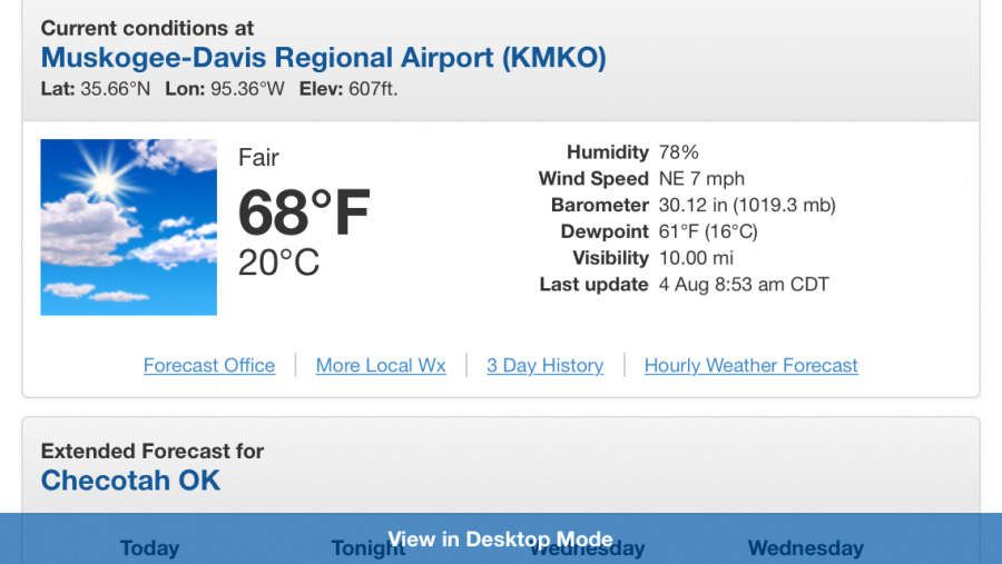
The elevation at Checotah is only about 600’...... so if there is a high pressure system in the area, you can def see baro readings over 30”...... like right now.
Posted By: Al_Alguire
Re: 508” KB – B1 build - 08/04/20 02:57 PM
I have been there plenty and have seen the actual at 29.1-5 like Tulsa Raceway typically. But who knows, corrected I can see it obviously/ just checked current in Tulsa is 29.45, it is 619' elevation. Just an observation but would think if its manometer reading it would be actual not corrected

Posted By: 440Jim
Re: 508” KB – B1 build - 08/04/20 03:17 PM
I asked him last night about those Man_P and Man_V and he said they weren't hooked up, so not sure what they are or what they were measuring..
It was raining on Friday so he did hook up the air plenum to a vent that pulls air from control room where he had a window A/C unit running. It wasn't very cool in there but the air was much dryer, he said pulling air from outside with the rain would be pointless as it would never run in the rain.
Wade,
Do you know if the air supply to the engine room has a fan forcing air into the room? Without one, the pressure in the room could drop as the exhaust pumps the room pressure down.
"Man_P and Man_V not hooked up" Does that mean the sensor(s) were hanging in the engine room? i.e. just not installed on the engine
If the engine room pressure was dropping due to duct restriction, that could explain lower power and the flatter torque. Assuming the dyno correction factor assumed the pressure constant (ambient/outside).
You’re right, what you want is the “observed” baro reading on site.
But there won’t be much correction difference between 29.5 and 30.0.
Certainly not enough to explain the massive CF on that sheet.
The elevation correction for 600’ is .64 in/hg....... so if the corrected baro was 30.10”, the observed should be 29.46”.
I’d love to see an uncorrected sheet to see if for some reason there is an anomaly with the bsfc numbers.
The bsfc is supposed to be the result of fuel flow divided by the uncorrected HP.
So, on the last line of the sheet the fuel flow is 356.4lbs/hr, and the result is .512.
For the result to be .512, the uncorrected power would be 696hp.
The corrected HP of 859.1 is just over 23.4% higher than 696.
If you look at Greg’s dyno sheet, which is in a town that’s about 300’ higher than where Wades motor was tested(and the sheet shows the baro as 29.13”), looking at the fuel flow and bsfc numbers you get an uncorrected power number of 830.8.
The corrected number is 921.5, which works out to a 10.9% CF.
So, how is it that Wades motor, which was tested at a facility that sits at a 300’ lower elevation, and had a higher observed baro pressure...... ends up with what appears to be a nearly 13% higher CF?
What am I missing there?
I asked him last night about those Man_P and Man_V and he said they weren't hooked up, so not sure what they are or what they were measuring..
It was raining on Friday so he did hook up the air plenum to a vent that pulls air from control room where he had a window A/C unit running. It wasn't very cool in there but the air was much dryer, he said pulling air from outside with the rain would be pointless as it would never run in the rain.
Wade,
Do you know if the air supply to the engine room has a fan forcing air into the room? Without one, the pressure in the room could drop as the exhaust pumps the room pressure down.
"Man_P and Man_V not hooked up" Does that mean the sensor(s) were hanging in the engine room? i.e. just not installed on the engine
If the engine room pressure was dropping due to duct restriction, that could explain lower power and the flatter torque. Assuming the dyno correction factor assumed the pressure constant (ambient/outside).
Jim, the SF system is reading the baro pressure in real time.
Though, where the sensor is on that particular SF system....... I’m not sure.
But it would be reading the pressure of wherever it was.
Posted By: 440Jim
Re: 508” KB – B1 build - 08/04/20 03:39 PM
In my experience, the weather reporting (typically from airports) publishes the barometric pressure corrected to sea level. This is so the aircraft can set their altimeter to show elevation above mean sea level (MSL); it would show 600 ft while on the ground at that airport. 600 ft MSL would correct the actual measurement of 29.46"Hg to 30.10"Hg [reported]
14.78 psi = 30.10"Hg (units conversion) not MSL correction
14.47 psi = 29.46"Hg
Dwayne, we may be putting 2 + 2 together. If the engine room pressure was dropping, the dyno correction factor would change noticeably if the SF system has a real time sensor near the engine/carb.
I think something like that is going on.
But having the room pressure change that much during a pull sure adds a lot of variables to the corrected result.
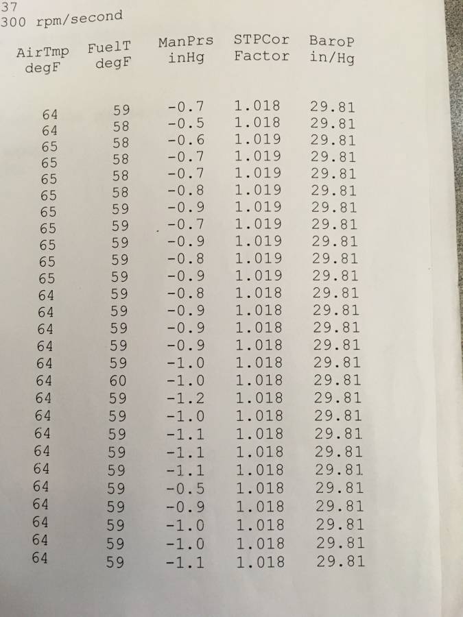
There is a channel in the software for the baro reading, which can be displayed on one of the sheets if desired.
We put it on the uncorrected data page here.
It rarely changes much at all throughout a pull.
Posted By: WadeMetzinger
Re: 508” KB – B1 build - 08/04/20 04:31 PM
I asked him last night about those Man_P and Man_V and he said they weren't hooked up, so not sure what they are or what they were measuring..
It was raining on Friday so he did hook up the air plenum to a vent that pulls air from control room where he had a window A/C unit running. It wasn't very cool in there but the air was much dryer, he said pulling air from outside with the rain would be pointless as it would never run in the rain.
Wade,
Do you know if the air supply to the engine room has a fan forcing air into the room? Without one, the pressure in the room could drop as the exhaust pumps the room pressure down.
"Man_P and Man_V not hooked up" Does that mean the sensor(s) were hanging in the engine room? i.e. just not installed on the engine
If the engine room pressure was dropping due to duct restriction, that could explain lower power and the flatter torque. Assuming the dyno correction factor assumed the pressure constant (ambient/outside).
You guys are talking way over my head...lol
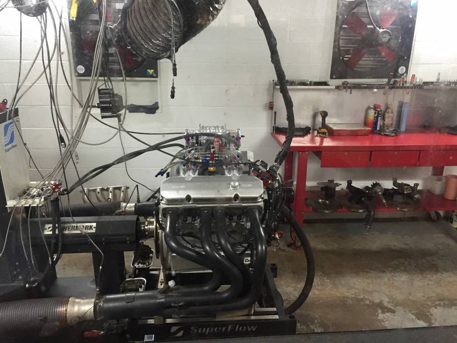
Here is a picture of the dyno room, there are 2 really high speed fans that he uses when making pulls, one pushes air in and one pulls air out. And then like I said below the plenum pull from a vent from the control room. (this picture is from a few years ago when I built that 572 B1 Drag Week motor with Monte Smith)
Posted By: Al_Alguire
Re: 508” KB – B1 build - 08/04/20 04:36 PM
Well I can tell you my last visit to an unknown to me dyno was nothing less than a gong show from start to finish. In short we quit quite early as none of the numbers it was spitting out made any sense. So we just called it a day and loaded up and went home. IN retrospect maybe the HP number was closish to reality but nothing else made or makes any sense to this day. Specifically the BSFC numbers. I was ready to pull it after two small pulls based on what I saw. In the end in my case I believe it was more a function of a far out of date dyno that had its fair share of software issues. That engine has been 4.65 148.98 in Vegas in our 4 link dragster on a 112 degree evening a couple weeks back. DA was almost 6000' barometer was 27.74 so maybe it was close on HP but that was about it..Numbers correct to a way better engine than I though we had leaving the dyno. Still needs a converter as its way tight and some further tuning but it runs pretty well for a pretty mild deal.
So I guess what I am saying is this would not be the first time I have seen numbers that make no sense on a dyno sheet. Its only a tool and only as good as the guy running it and the software supporting it. Wade will know once he gets it in the car what kind of power it truly makes for HP and Scales never lie

Maybe we are just reading way to much into what's there, not without reason mind you but sometimes things just dont work as they should.
Posted By: Cab_Burge
Re: 508” KB – B1 build - 08/04/20 04:42 PM
The elevation at Checotah is only about 600’...... so if there is a high pressure system in the area, you can def see baro readings over 30”...... like right now.
All barometer readings at any reporting airport are corrected to sea level readings, not the actual barometer reading, so all airplane altimeters are reading alike when landing at that airport.
The FAA decided that long ago

All airplane flying above 18,000 Ft are suppose to set their altimeter to 29.92 until they are ready to land and then descend below 18,000 Ft.
Al, what you’re describing is exactly why I say it’s never a good idea to compare numbers from different dynos.
Many times it’s not a fault of the dyno at all........ but a room that’s got some strange things going on.
If a motor I test goes into a car that’s really well set up(hooks, has the right gears, good converter, no fuel system woes, etc), and it’s being raced in “decent” air, the numbers will be very close to what the Moroso chart shows.
It happens that way sometimes, but it’s the exception rather than the rule.
What I use as a general rule to see if you’re even in the ball park is 90% of the corrected hp...... in “reasonable” air(not mineshaft air).
As an example....... 800STP power, 2800lb car, DA around 2500’, temps in the 70’s.......,the number on the Moroso chart should be 720hp(800 x .90) or better(800hp would be an 8.65@155....... while 720hp would be a 9.05@149.5)
If you can’t get it to come that close(or better), there’s a good chance you might have some happy dyno numbers.
If you run at tracks high enough in elevation to use a correction factor....... then that has to be figured into the result as well.
Posted By: Al_Alguire
Re: 508” KB – B1 build - 08/04/20 05:42 PM
Dwayen, trying figuring it out at altitude tracks like we have all over the west. Vegas is a solid .25 slower than say Sonoma, which is a solid .1-.15 slower than say Cecil, MIR or any number of east coast tracks I have run. When we first started coming to the midwest running the heads up car in the summer we expected to not run very well. But the barometer usually makes up for any shortcomings that the Humidity, Grains and VP might bring. We run generally better than we ever run out west. Partly due to the tracks but mostly the barometer back here. I have yet to run my car since coming to Ohio but the Wheatcratfs tell me to expect .1-.15 better Et in the summer here in the1/8 than "great" Vegas air. Guess what I am getting at is "decent" air on many of the east coast facilities I have been to is better than great air out west. Morale of the story is while the moroso calculator is yet another tool it cannot account for many variables that we all are keenly aware of. DA is not just DA alot goes into figuring that number and certain things, like barometer in particular play a very large role in how well a car will run. I can tell you that typical 4000' DA day in Vegas is going to be at least .3 slower than that same typical 4000'DA in say Norwalk. I have run in both. Just something to consider when we see posted ET slips and such.
Posted By: CSK
Re: 508” KB – B1 build - 08/04/20 06:07 PM
I asked him last night about those Man_P and Man_V and he said they weren't hooked up, so not sure what they are or what they were measuring..
It was raining on Friday so he did hook up the air plenum to a vent that pulls air from control room where he had a window A/C unit running. It wasn't very cool in there but the air was much dryer, he said pulling air from outside with the rain would be pointless as it would never run in the rain.
Wade,
Do you know if the air supply to the engine room has a fan forcing air into the room? Without one, the pressure in the room could drop as the exhaust pumps the room pressure down.
"Man_P and Man_V not hooked up" Does that mean the sensor(s) were hanging in the engine room? i.e. just not installed on the engine
If the engine room pressure was dropping due to duct restriction, that could explain lower power and the flatter torque. Assuming the dyno correction factor assumed the pressure constant (ambient/outside).
I think 440Jim nailed it, years ago we had a similar thing happen in a very small dyno room.
Okay....... so let’s say there is an “air supply” problem in the dyno room, and the air pressure in the room is dropping as the run progresses, and as a result of that, the dyno software is adjusting the CF accordingly.
How does that situation change how the motor responds to the tuning changes?
The dropping air pressure would affect how effectively the motor takes in air, as well as how the carb meters fuel.
It’s hard for me to imagine an in car scenario where the engine would see the pressure at the carb drop significantly during a pass.
If you had any kind of effective scoop....... the opposite should be happening.
Posted By: Cab_Burge
Re: 508” KB – B1 build - 08/05/20 12:53 AM
Two of the DTS engine dyno shops I use to use in SO CA had positive dyno room pressure with the intake and exhaust fans running with the engine being tested running at idle or anything less than WOT

Once I figure out that meant the motor being tested had from 1 to 4 lbs. of boost being added at WOT I had them leave the dyno room doors open after that

I have seen them turn the inlet fans off after a pull and open the dyno room doors with the exhaust fans left on and then forget to turn the inlet fans back on before starting the next pull, they could tell the difference in sounds at WOT at the beginning of the pulls which would make them stop the pull to turn on those fans and restart the pull over


As W.J. the professor said many times , we don't race dyno, do we

Posted By: sr4440
Re: 508” KB – B1 build - 08/17/20 05:30 PM
I asked him last night about those Man_P and Man_V and he said they weren't hooked up, so not sure what they are or what they were measuring..
It was raining on Friday so he did hook up the air plenum to a vent that pulls air from control room where he had a window A/C unit running. It wasn't very cool in there but the air was much dryer, he said pulling air from outside with the rain would be pointless as it would never run in the rain.
Wade,
Do you know if the air supply to the engine room has a fan forcing air into the room? Without one, the pressure in the room could drop as the exhaust pumps the room pressure down.
"Man_P and Man_V not hooked up" Does that mean the sensor(s) were hanging in the engine room? i.e. just not installed on the engine
If the engine room pressure was dropping due to duct restriction, that could explain lower power and the flatter torque. Assuming the dyno correction factor assumed the pressure constant (ambient/outside).
Jim, the SF system is reading the baro pressure in real time.
Though, where the sensor is on that particular SF system....... I’m not sure.
But it would be reading the pressure of wherever it was.
the baro sensor is inside the control box.
Joe
the baro sensor is inside the control box.
Good to know...... thanks!!
And that box is in the dyno cell, correct?
On your 902, what are the ManP and ManV channels used for, and what would they be reading if you didn’t have the hoses attached to anything?
Any thoughts on the widely variable CF on that run?
Posted By: sr4440
Re: 508” KB – B1 build - 08/17/20 06:44 PM
the baro sensor is inside the control box.
Good to know...... thanks!!
And that box is in the dyno cell, correct?
On your 902, what are the ManP and ManV channels used for, and what would they be reading if you didn’t have the hoses attached to anything?
Any thoughts on the widely variable CF on that run?
I didn't see it on the sheet he posted, but mine make small adjustments during the run (0.01) because of the temps in the room going up 1/2 degree.
ok, seen your numbers, doesn't make sense because the baro sensor is in the control box right on top of the dyno. (FYI I also have a SF powermark) and he is getting outside air.
I would really like to have a copy of the data file.
edit the ManP and ManV is one pressure channel with a different way to look at the data -14.1 PSI is -28.70 inhg. 1 psi = 2.03602 inhg. But it shouldn't be moving around during a pull. It looks like pressure is building as the run goes on.
Joe
Posted By: sr4440
Re: 508” KB – B1 build - 08/17/20 06:48 PM
Wade
A few comments just looking at your dyno sheet.
1st did he weight your fuel? Because the default is .750 and renegae 112 is .711 @60 degrees F. So my 1st thought is your BSFC should be better unless the fuel was 40 degrees then it may have had a .750 SG
2nd did he tell you why he was running the Inertia correction factor at a 1.000?
Wade, I would ask him to email you a “customer data pack”. That has ALL of the data taken in by the dyno. Plus it allows you to do some post run corrections.
For those of you that don’t know what STPIPw and STPiTr are. It is corrected to STP J-607 and with inertia correction. Inertia correction is a factor added (or taken away from a decell test) the torque reading.
Why is inertia factor added? It has to do with Newtons 1st law of motion “an object either remains at rest or continues to move at a constant velocity, unless acted upon by a force”. When we do a sweep test on a Dyno, we have to accelerate the crankshaft, flywheel, drive plate, driveshaft and dyno brake. All of this takes energy and that energy can’t be measured by the brake because it being stored in all the rotating mass. Each engine has a different factor.
How do you determine the engines “Inertia factor”. You run a special sweep up and down, doesn’t have to be at full throttle. Now if you correction factor is right the HP and Tq lines will lay over each other, because we are correcting (by adding) for the energy being stored during accell and correcting (by removing) during decell. If the number is not right it can be adjusted during post analysis until it is correct.
So what have we done? Well now we can make a sweep at 200 rpm per second and 600 rpm per second and get the same HP reading. You can do a step test and get the same reading. Before a 750 rpm per second read would always have a lower HP reading than a 400 rpm reading per second run.
Joe
Posted By: CSK
Re: 508” KB – B1 build - 08/17/20 06:59 PM
Wade
A few comments just looking at your dyno sheet.
1st did he weight your fuel? Because the default is .750 and renegae 112 is .711 @60 degrees F. So my 1st thought is your BSFC should be better unless the fuel was 40 degrees then it may have had a .750 SG
2nd did he tell you why he was running the Inertia correction factor at a 1.000?
Wade, I would ask him to email you a “customer data pack”. That has ALL of the data taken in by the dyno. Plus it allows you to do some post run corrections.
For those of you that don’t know what STPIPw and STPiTr are. It is corrected to STP J-607 and with inertia correction. Inertia correction is a factor added (or taken away from a decell test) the torque reading.
Why is inertia factor added? It has to do with Newtons 1st law of motion “an object either remains at rest or continues to move at a constant velocity, unless acted upon by a force”. When we do a sweep test on a Dyno, we have to accelerate the crankshaft, flywheel, drive plate, driveshaft and dyno brake. All of this takes energy and that energy can’t be measured by the brake because it being stored in all the rotating mass. Each engine has a different factor.
How do you determine the engines “Inertia factor”. You run a special sweep up and down, doesn’t have to be at full throttle. Now if you correction factor is right the HP and Tq lines will lay over each other, because we are correcting (by adding) for the energy being stored during accell and correcting (by removing) during decell. If the number is not right it can be adjusted during post analysis until it is correct.
So what have we done? Well now we can make a sweep at 200 rpm per second and 600 rpm per second and get the same HP reading. You can do a step test and get the same reading. Before a 750 rpm per second read would always have a lower HP reading than a 400 rpm reading per second run.
Joe
Great info, Thank you Joe
Posted By: WadeMetzinger
Re: 508” KB – B1 build - 12/23/20 08:36 PM
Just a season end update....
The first time out at the track it ran 9.57 but at the end of the year it ran a 9.27 at 144.50mph.
No changes to the motor or tune up just slightly better weather and everything broke in nicely. Motor, tranny, gears were all new.
I need a new converter or just need mine adjusted, I ran most of the season with my 5,400 2 step chip in the box and then I check the stall and found out it was only stalling to 4,800. The torque is down from the other motor and moving from alcohol to gas lost torque as well.
Posted By: Cab_Burge
Re: 508” KB – B1 build - 12/24/20 12:47 AM
Just a season end update....
The torque is down from the other motor and moving from alcohol to gas lost torque as well.
Are you sure it is the alcohol causing the loss of stall?
I've dyno tested pump gas against E85 and loss 12 HP (688 HP VS 676 HP at 6700 RPM) with E85 and gained 37 Ft. lbs. torque going from 635 Ft. Lbs. to 669 Ft. Lbs.

Posted By: 440Jim
Re: 508” KB – B1 build - 12/24/20 01:26 PM
Just a season end update....
I need a new converter or just need mine adjusted, I ran most of the season with my 5,400 2 step chip in the box and then I check the stall and found out it was only stalling to 4,800. The torque is down from the other motor and moving from alcohol to gas lost torque as well.
That is my general understanding as well. Alky makes more torque than gasoline, so when you switched to gas it lost some torque. 4,800 stall is low for that combo; it will run quicker with more stall.

Sounds like there’s a bit left in it with a converter update.
You’re sneaking up on it:


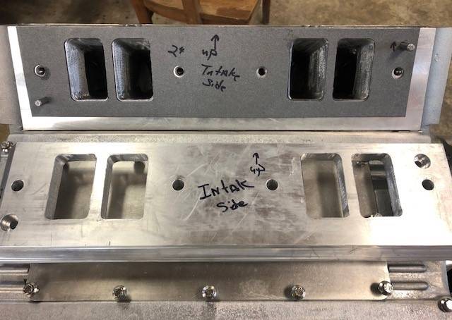
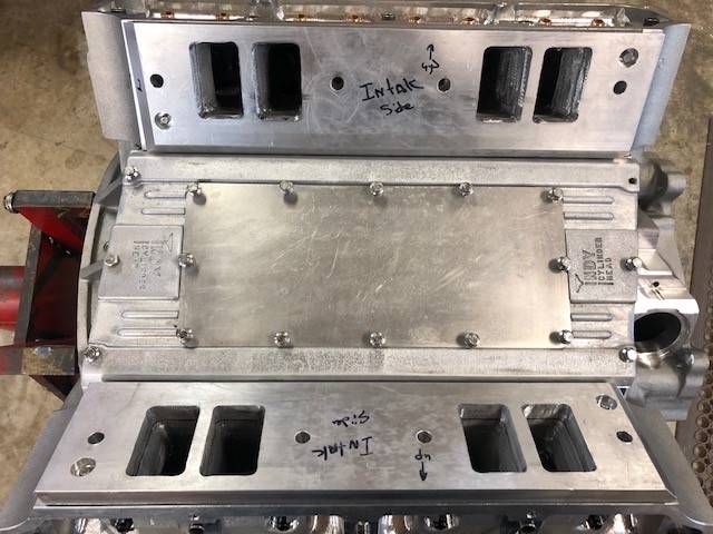
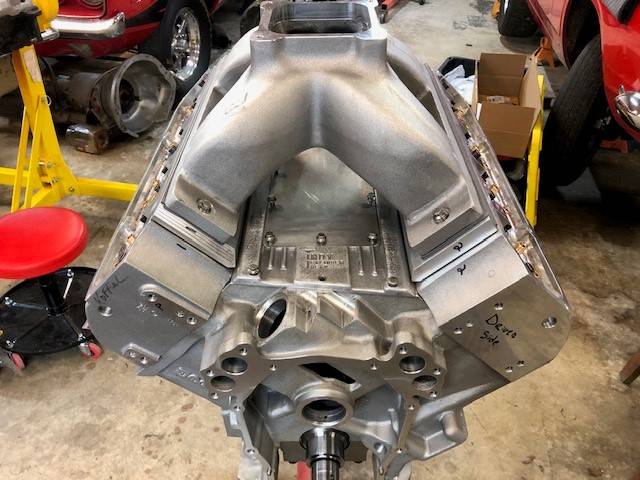


![[Linked Image]](https://i.postimg.cc/wvVVjTqH/image.jpg)
![[Linked Image]](https://i.postimg.cc/tCmB6Th4/7-E98-B8-C5-E405-440-A-8-A30-4-C90-A61447-AA.jpg)


![[Linked Image]](https://i.postimg.cc/TYtRpBDm/785-CA943-0-F44-41-F7-BDC4-E7673-AAC0466.jpg)


