Moparts

Electrical upgrades

Posted By: GY3

Electrical upgrades - 01/08/20 02:19 AM

Going to do the bypass of the bulkhead with a 10 gauge wire and fusible link.

I keep seeing conflicting info. on the best place to run the wire from the BAT terminal on the alternator.

Some say the relay, some say stud on the starter and some say the positive post on the battery. While I realize all those locations lead back to the battery, is there one location that is better than another?
Posted By: CSK

Re: Electrical upgrades - 01/08/20 03:12 AM

I ran an 8 gauge to the stud on the starter relay, from the 130 amp alt, works great on my 68 Charger.
Posted By: CMcAllister

Re: Electrical upgrades - 01/08/20 04:04 AM

I'm assuming rear mount battery. If it doesn't need a legal, functional master switch, I would want to keep it short and run it to the closest terminal stud for the main battery cable - starter relay, junction block, etc. Not the starter to avoid clutter & hot pipes, not all the way to the trunk to avoid that long run (voltage drop). If it has a master switch that you want to work correctly - run it to the battery side stud on the switch or the battery itself and consider going up a size because of the distance.
Posted By: GY3

Re: Electrical upgrades - 01/08/20 04:13 AM

Originally Posted by CMcAllister
I'm assuming rear mount battery. If it doesn't need a legal, functional master switch, I would want to keep it short and run it to the closest terminal stud for the main battery cable - starter relay, junction block, etc. Not the starter to avoid clutter & hot pipes, not all the way to the trunk to avoid that long run (voltage drop). If it has a master switch that you want to work correctly - run it to the battery side stud on the switch or the battery itself and consider going up a size because of the distance.


No, battery is still up front in the stock location.
Posted By: crackedback

Re: Electrical upgrades - 01/08/20 04:53 AM

When I do the wire arounds I sell, I do them to attach at the starter relay. Make sure the feed wire back to battery is in good shape.

Run min. 8ga wire and 12ga fusible link. The factory wire is 10ga IIRC.

Just my 2 cents
Posted By: dvw

Re: Electrical upgrades - 01/08/20 03:27 PM

I actually removed the terminals at the bulk head. That's where the problem is. Drill thru the bulkhead and run the 10 gauge right thru the holes previously occupied by terminals. Leave the wire a little long on the interior side before splicing to the dash harness. That way if you have to remove the harness there is enough length to resplice. I've run a 110 amp alternator in my Challenger this way 16 years with no issue.
Doug
Posted By: Bad340fish

Re: Electrical upgrades - 01/08/20 04:40 PM

Originally Posted by dvw
I actually removed the terminals at the bulk head. That's where the problem is. Drill thru the bulkhead and run the 10 gauge right thru the holes previously occupied by terminals. Leave the wire a little long on the interior side before splicing to the dash harness. That way if you have to remove the harness there is enough length to resplice. I've run a 110 amp alternator in my Challenger this way 16 years with no issue.
Doug


That is probably the best way to do it right there!

I got rid of all the factory wiring except for lights and wipers, but if I had retained more I would do exactly what DVW said. I would feel better with a circuit breaker or a fuse than a fusable link though, that is just me.
Posted By: CMcAllister

Re: Electrical upgrades - 01/08/20 05:57 PM

I prefer a fuse to a fusible link. Reliable circuit protection. A simple fuse replacement as opposed to a harness repair in the event of a problem. MIDI style fuses are available in the amp rating you desire.

I would also be inclined to cut and terminate the alternator power line to the battery terminal on the starter relay, and continue the run to the interior of the car from that point. Not remove the power feed through the dash, but give the alternator feed line a more direct path to the battery.
Posted By: GY3

Re: Electrical upgrades - 01/08/20 08:36 PM

Originally Posted by CMcAllister


I would also be inclined to cut and terminate the alternator power line to the battery terminal on the starter relay, and continue the run to the interior of the car from that point. Not remove the power feed through the dash, but give the alternator feed line a more direct path to the battery.


That's the plan!
Posted By: B Dartman

Re: Electrical upgrades - 01/09/20 01:58 AM

Yo up

Did same mod to Dart couple years ago when switching to the Denso alternator. Couple key points to note as others posted: 1) Drill out the bulkhead connector and feed the new wires through (eliminates a known problem area) 2) Have a look at the below info regarding "remote voltage sensing" and "by-passing Amp Gauge"; in the case of the Dart installed a terminal post under dash and ran the sensing wire to this location (e.g. may be good to install near MSD box) so that the voltage is being monitored close to where you have the most concern it's maintained. 3) In regards to fuses I'm using blade type fuses (easy to replace/readily avail), but for your race application might want to go with the suggested MIDI.

Remote Voltage Sensing

By-Passing Amp Gauge

SIngle Wire vs. Three Wire

beer
Posted By: Cab_Burge

Re: Electrical upgrades - 01/09/20 02:06 AM

I had the 10 gauge wire from my 100 Amp alternator on my bracket car melt after the timing light 12V feed wire I had clip onto the alternator output wire grounded out, it smoked that 10 gauge wire in a big hurry puke
I called Power Master about having them look at my alternator to see if it was hurt or not ( I ended up replacing the 10 wire with another one that size and ran the motor, the alternator is still putting out 14.5 V revved up above 1500 RPM up) and during that discussion the tech told me to use a #4 gauge wire, not a 10 gauge, to the battery, he also said to make sure and ground the alternator with a #4 wire to a threaded bolt hole in the block from the threaded ground hole from the alternator boss shock up
I'm planning on doing both of those changes this winter wrench up Along with several other changes to make the car faster and easier to race and make changes at the track luck wrench
Posted By: CMcAllister

Re: Electrical upgrades - 01/09/20 03:33 AM

Quote
the tech told me to use a #4 gauge wire


shock That's used for battery cable on a lot of cars. Depending on the length of the run.
Posted By: Dave_J

Re: Electrical upgrades - 01/09/20 07:39 AM

I ran a 6 gauge from my Alt to the Starter relay lug. All my battery cables are 2 gauge.
I am one of the 'Amp' meter by-passers.
Posted By: GY3

Re: Electrical upgrades - 01/09/20 02:50 PM

Originally Posted by B Dartman
Yo up

Did same mod to Dart couple years ago when switching to the Denso alternator. Couple key points to note as others posted: 1) Drill out the bulkhead connector and feed the new wires through (eliminates a known problem area) 2) Have a look at the below info regarding "remote voltage sensing" and "by-passing Amp Gauge"; in the case of the Dart installed a terminal post under dash and ran the sensing wire to this location (e.g. may be good to install near MSD box) so that the voltage is being monitored close to where you have the most concern it's maintained. 3) In regards to fuses I'm using blade type fuses (easy to replace/readily avail), but for your race application might want to go with the suggested MIDI.

Remote Voltage Sensing

By-Passing Amp Gauge

SIngle Wire vs. Three Wire

beer


Thanks, Bill!
Posted By: krautrock

Re: Electrical upgrades - 01/09/20 03:41 PM

i used 8ga on my truck, alt b+ runs to the lug on the relay, then from there i feed into the cab bypassing the bulkhead (coz it was melted at the terminals). used 12ga fusible wire as well.
ordered one of the repro Denso style alternators, just looking for 60amp output, the test sheet shows the alt puts out 120amps at 13.5V...hope my 8ga wire is ok.
Posted By: Mattax

Re: Electrical upgrades - 01/09/20 03:51 PM

Originally Posted by GY3
I keep seeing conflicting info. on the best place to run the wire from the BAT terminal on the alternator.

It depends on what is the most important equipment to feed in your setup and use.
For example, If the system has had additional electrical items added, such as electric fans, fuel pumps, EFI the situation is different.
Or for example if race will be run on battery power, or .. or ...

Originally Posted by GY3
Going to do the bypass of the bulkhead with a 10 gauge wire and fusible link.

That would be fine in most cases. The fusible link protects against the battery burning up big wires if any of them are accidently grounded.

Keep in mind the battery was not really meant to power the car car after starting.
Under normal running conditions the alternator powers the car. That's why the alternator output stud "BATT" was wired to the main splice first on the older cars. In the mid-70s Chrysler started to split the power up on the engine side of the firewall, so there was no longer a single main splice. But the concept remains the same. Power comes from either the alternator or the battery. Whichever one has the higher voltage.

If the battery is being run down, then it will draw more current during recharge. Feeding the recharge direct may make sense, as it shortens the route and the connections.
Feeding the main splice from the alternator by routing to the battery first creates a longer path with more connections. But in some situations that may not be important.


Posted By: Mattax

Re: Electrical upgrades - 01/09/20 04:05 PM

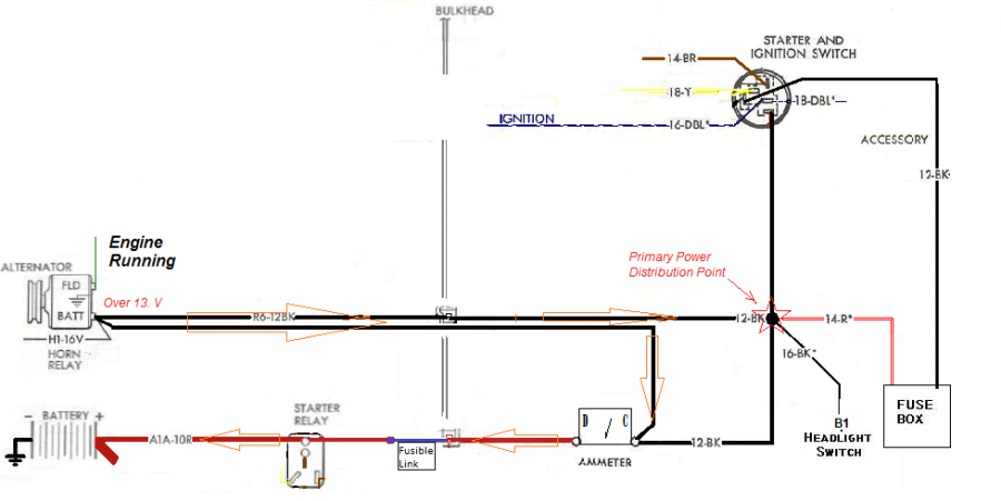
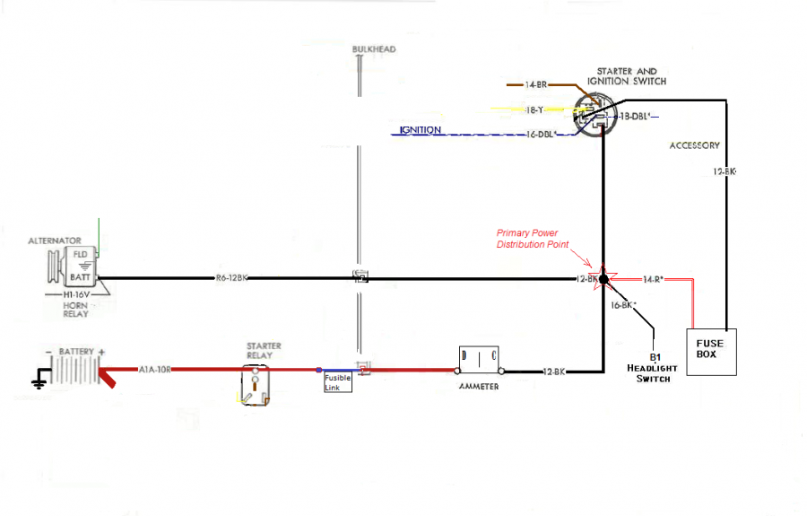
Basic Power Supply Scheme or Strategy.
There are two power sources, alternator and battery.
Each connects to the main power distribution point (or points).

The battery feed also serves as the recharge line.
No fusible link was provided on the alternator output because if there is a short to ground the alternator and engine will generally stop running.


Attached picture Basic-Power-diagram6x-p.png
Posted By: Mattax

Re: Electrical upgrades - 01/09/20 04:26 PM

Originally Posted by krautrock
i used 8ga on my truck, alt b+ runs to the lug on the relay, then from there i feed into the cab bypassing the bulkhead (coz it was melted at the terminals). used 12ga fusible wire as well.
ordered one of the repro Denso style alternators, just looking for 60amp output, the test sheet shows the alt puts out 120amps at 13.5V...hope my 8ga wire is ok.

Actual output from battery or alternator depends on the load.

In other words, whatever items are using electricity are primary determiner.
The second determiner is the voltage at which the items get the power.
For example, if power is provided at 14 Volts while the engine is running.
Ignition and field need 4 amps (1960s ignition and alternator)
Headlamps and markers draw around 12 amps

So driving at night, the alternator output would be 16 amps.

The only danger of a high output capability is if the battery is run down.
Batteries will draw current for recharging in proportion to the charge state.
A fully discharged battery, offered power at 14 Volts, may try to draw 40, 50, 60 amps or more!
Most of the factory alternators in the 60s and even 70s couldn't provide that, at least at idle, so the system was somewhat self protecting.
Posted By: Mattax

Re: Electrical upgrades - 01/09/20 04:36 PM

Originally Posted by krautrock
ithe test sheet shows the alt puts out 120amps at 13.5V

PS. If the test was run at 14.5 Volts, max output would have been less than 120.
Its not major, but makes it harder to compare. 120 amps x 13.5 V = power. Then divide by 14.5 Volts to get the current and the new voltage.

Chrysler's factory specs were done at 15 Volts (see your shop manual), so the output current looks lower when compared to a test made at 13.5 Volts.
The shop manual test was also usually done at 1250 rpm, whereas the ratings are usually done at high rpm. Again making it hard to compare. Sometimes the FSM lists both, sometimes not.
Posted By: GY3

Re: Electrical upgrades - 01/09/20 04:43 PM

Originally Posted by Mattax
Originally Posted by GY3
I keep seeing conflicting info. on the best place to run the wire from the BAT terminal on the alternator.

It depends on what is the most important equipment to feed in your setup and use.
For example, If the system has had additional electrical items added, such as electric fans, fuel pumps, EFI the situation is different.
Or for example if race will be run on battery power, or .. or ...


Very minimalist setup. Small electric supplemental fuel pump and small nitrous control board. other than that, it is similar to a factory 1963 setup. No stereo, electric fans, fuel injection, etc.
Posted By: Mattax

Re: Electrical upgrades - 01/09/20 05:42 PM

If the supplemental electric pump is only run when the engine is running, then the factory scheme is actually very good.
Power the supplemental pump direct from the alternator with a relay that turns on with key in run. Use a fuse in the line
or if the draw is low enough, its possible to add a fuse to the fuse box. Its just a pain.

Headlights if used, also benefit from direct from alternator through a relay.
There's a lot of connections for the electricity to get to the headlights - and on a-bodies especially, the wires are small.

Depending on the condition of your firewall connector, for your needs a parallel wire to the ammeter's stud might be enough. Use a well insulated ring terminal.
If the bulkhead connectors are poor, then remove the alternator feed wire from the bulkhead inside and tie in a new 8 or 10 gage wire through a grommet in the firewall.
If the battery feed connection is also poor, then 10 gage with 16 gage fusible link on engine side, then 10 gage through a grommet to the ammeter red terminal.

I thought '63 had the better bulkhead connector, but maybe that was just '65. shruggy
Posted By: Mattax

Re: Electrical upgrades - 01/09/20 05:47 PM

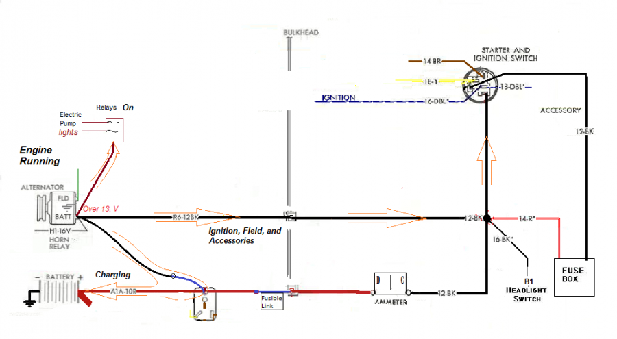
This is a parallel alternator feed through a grommet.
At minimum it means any current for recharging the battery will have a dedicated route from alternator.

Illustration showing battery charging

Attached picture Basic-Power-diagram6x-p-running-pll-charge.png
Posted By: Mattax

Re: Electrical upgrades - 01/09/20 06:16 PM

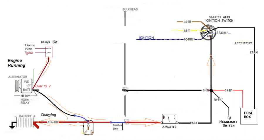
Doing it as above means only one fusible link is needed.
It also lets you monitor the battery charging and discharging.

Connecting the Alternator output direct to the battery or tying in at the starter relay does the same thing.
It gives the sometimes high charging current a seperate route to the battery, reducing the load on the main feed wire and connections.
Difference is that a fusible link is needed in the connecting line to protect against battery grounding, and the ammeter will no longer show charging.

Attached picture Basic-Power-diagram6x-bypass-charging.png
Posted By: Cab_Burge

Re: Electrical upgrades - 01/09/20 06:19 PM

Originally Posted by Mattax

Difference is that a fusible link is needed in the connecting line to protect against battery grounding, and the ammeter will no longer show charging.

That is why I put a volt meter in my race car to make sure the alternator is working up
Easy peasy to do also up
I connected it to the ignition feed, shows battery voltage before starting and alternator charging voltage when running thumbs
Posted By: Mattax

Re: Electrical upgrades - 01/09/20 06:22 PM

Some places encourage removing the alternator's feed to the main splice.
This creates a longer path through two fusible links with more connections for everything but battery recharging.
Not recommended unless running battery most of the time.

Attached picture Basic-Power-diagram6x-bypass-MAD.png
Posted By: furious70

Re: Electrical upgrades - 01/09/20 06:41 PM

When I went EFI on my Fury, the main criteria for rewire were:

Remove the battery charging circuit from the cabin (e.g. amp bypass, bulkhead bypass)
consolidate new power needs (efi, fuel pump, stereo, etc) on a bus and draw voltage 'sensing' from that bus

so I
bypassed amp gauge
rerouted alt output to the big post on the starter relay
efi, fuel pump, stereo draw power from the big post
allowed OEM wiring to still feed the cabin - in this case I created 2 parallel paths for power to flow from the source (alt or batt) into the cabin vs the OEM in and out
I actually didn't bypass the bulkhead, I repaired it and since I removed all draw from that circuit except the OEM equipment in the cabin and removed the battery charging from that circuit, there's no issue

I used a 1 wire alt, if not I would have run the sensing wire to the big post as well.
Posted By: CMcAllister

Re: Electrical upgrades - 01/09/20 07:33 PM

Bypassing the problematic, old, original ammeter and using a voltmeter to monitor the electrical system is an easy decision for me, regardless how it is wired.
Posted By: Dave_J

Re: Electrical upgrades - 01/10/20 12:35 AM

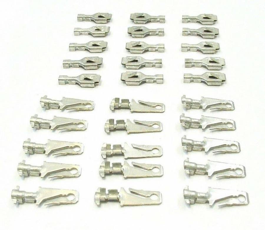
If you need new crimp spade connectors for your bulkhead block you can get some off Ebay. These are medium duty so they are OK for all but the 10 Gauge wires. I do not know where to get the heaver ones.
https://www.ebay.com/itm/Mopar-Male-Female-14-16-AWG-Gauge-Wiring-Harness-Terminal-Crimp-Connectors-NOS/192502001151?ssPageName=STRK%3AMEBIDX%3AIT&_trksid=p2057872.m2749.l2649

Attached picture Spades.jpg
© 2024 Moparts Forums