Posted By: 1DGEMAN
1970 CUDA ROAD LAMP WIRING DIAGRAM - 08/27/16 02:19 AM
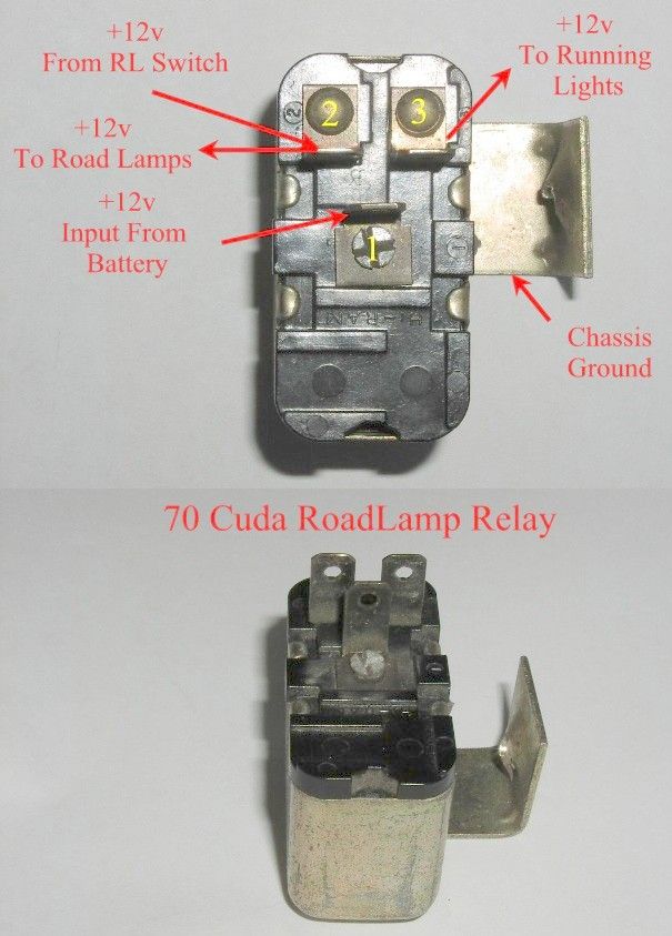
There is no diagram in the 70 manual and the 71 is different. I have 2 under dash harnesses and 2 relays. I get power to the lights if I unplug the relay. Testing both relays the terminal where the green road lamp wire goes is grounded with an internal connection to the relay case. The pink wire goes to power and the yellow wire goes to power something is wrong. HELP.
Posted By: screamindriver
Re: 1970 CUDA ROAD LAMP WIRING DIAGRAM - 08/27/16 04:50 AM
Here's the pic that used to get passed around for the 70 road lamp harness...

Posted By: DAYCLONA
Re: 1970 CUDA ROAD LAMP WIRING DIAGRAM - 08/27/16 05:00 AM
If you need a section magnified, let me know
1970 dash wiring

Posted By: 1DGEMAN
Re: 1970 CUDA ROAD LAMP WIRING DIAGRAM - 08/27/16 05:29 AM
Thanks guys I have seen both of those. The first diagram is under hood no problem there.In the pic Screamin posted if you look at the relay you can see the solder that connects directly to the green wires in the plug which should be isolated and switched 12v. The yellow wire also hooks into 12v a does the pink wire.
The second diagram shows just power to the switch and out to lights which makes perfect sense but doesn't conform to the so called "road lamp wiring harness and relay"
I think I will eliminate the harness and wire it like the second diagram. I was hoping I had missed something.
Posted By: 5carguy
Re: 1970 CUDA ROAD LAMP WIRING DIAGRAM - 09/05/16 11:51 PM
Not to hijack this thread but how about the 71 road lamp diagrams.
TIA
Posted By: screamindriver
Re: 1970 CUDA ROAD LAMP WIRING DIAGRAM - 09/06/16 03:33 AM
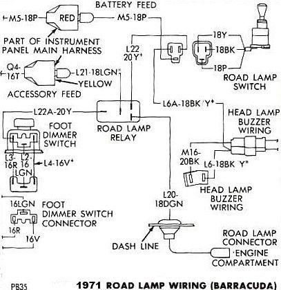
Here it is with a nice green backround..

Posted By: cataclysm80
Re: 1970 CUDA ROAD LAMP WIRING DIAGRAM - 09/06/16 07:13 AM
Just in case it wasn't clear to everyone, The green background diagram above ^ is for 1971.
Here's a white background copy of it that's also labeled as 1971.
Posted By: cataclysm80
Re: 1970 CUDA ROAD LAMP WIRING DIAGRAM - 09/06/16 07:15 AM
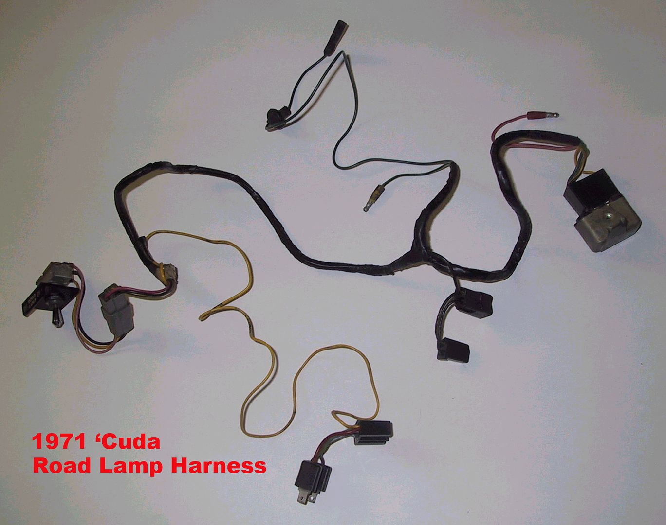
Here's a pic of my 1971 Road Lamp Harness
Posted By: cataclysm80
Re: 1970 CUDA ROAD LAMP WIRING DIAGRAM - 09/06/16 07:16 AM
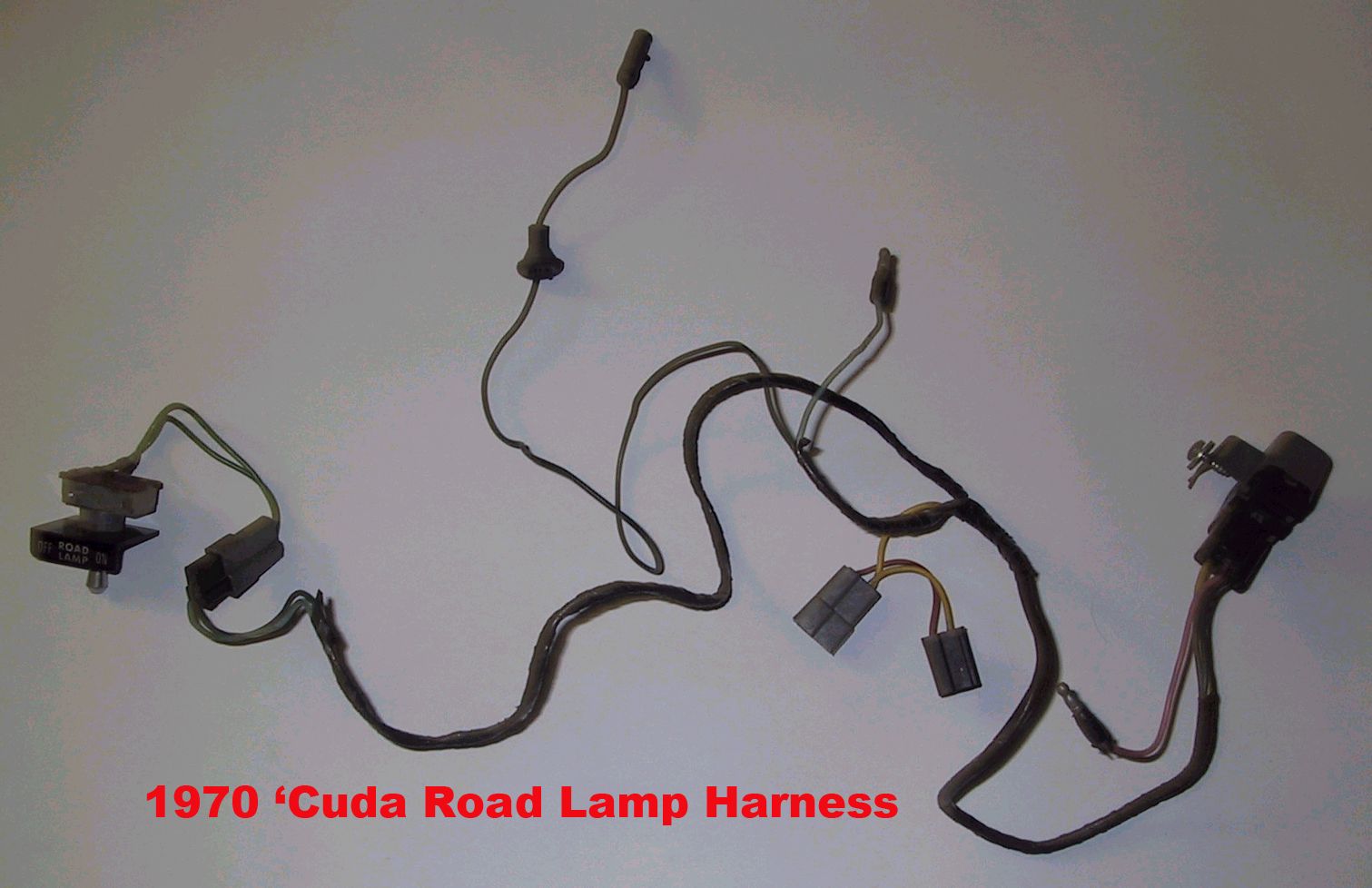
Here's a pic of my 1970 Road Lamp Harness
Posted By: cataclysm80
Re: 1970 CUDA ROAD LAMP WIRING DIAGRAM - 09/06/16 07:20 AM
Here is the other pic which goes with the 70 Harness pic that screamindriver already posted above.
(nice to see you again screamindriver, and you too Dayclona

)
Posted By: cataclysm80
Re: 1970 CUDA ROAD LAMP WIRING DIAGRAM - 09/06/16 07:39 AM
I don't log into Moparts as much as I have in years past, so it's been a long while since I looked over any of this Road Lamp stuff. Please take the following info with a grain of salt, but hopefully it will help you figure out what's going on.
I do remember that road lamp relays regularly cause confusion.
If I remember correctly, the main issue was that people expect the relay to turn the road lamps on, when actually it's purpose was to turn the road lamps off when the high beams came on.
If your road lamps come on when you unplug the relay, then maybe your highbeams are on?
Most of the following info was saved from a previous Moparts thread over a decade ago. That's where the 70 harness pic screamindriver posted came from...
L34 Road Lamps
The cuda road lamp moutning brackets and the Switch and relay are different between 70' and 71'
In 1970 the relay controls parking and side marker lights as well as the lights on reminder buzzer, 1971 controls the above plus the road lamps.
If I read that diagram right the relay has nothing to do with the buzzer. The buzzer is attatched to the switch. Correct, however the relay is not a stand alone circuit, nothing in the circuit works without the Road Lamp Switch.
The relay applies power to the lights and they are turned off by the relay when the highbeams are on. - The Road Lamp Switch applies power to the relay which applies power to the lamps. The foot dimmer switch will turn off the roadlamps if the high beams are turned on.
If the lights/switch is left on the buzzer buzzes same as the headlights. Right/Wrong? If the Road Lamp Switch is left on it will trigger the buzzer, the headlamp on buzzer is triggered by the parking/side marker lights that are turned on when either the headlight or Road Lamp Switch are turned on.
In 1970 the switch turned on the roadlamps directly.
70 relay does only have 3 terminals 71 relay has 4 terminals plus the extra wiring/connectors going down to the dimmer switch
1970 relay circuit have the following leads.
L20 and L20A - Lamp out and power direct from the switch.
L6 and L6A - Park and side marker lamps and Headlight buzzer diode
L21 - N/A
M5A - Power
Q13 - Headlight buzzer diode
relay part #s '70 - 3004186
'71 - 3513557
Key and headlight buzzer the same in '70
Are 70 road lamp brackets the same as 71?
No, they are not the same. 1970 versions are a two piece bracket (two parts welded together). 1971 style is the same basic shape but a single piece stamping. BTW, original 71's are really hard to find!
How do I figure out if its an original road lamp bracket Any P/N or Pentastars to look out for?
1970 roadlamp(two piece welded together)brackets had an "R" or "L", but 1971 (one piece)brackets had "RH" or "LH" for left or right hand. that's it, no other numbers. There are some reproductions that have them as well. The key to ID'ing the reproductions is that they were not stamped as originals, they were laser or water cut and have serrated edges accordingly rather than the pinched through-sheared look of a stamped parts edge.
