Moparts

Chrysler Engineering Drawings with 0 inch reference

Posted By: 6bblgt

Chrysler Engineering Drawings with 0 inch reference - 04/11/13 03:41 AM

On the various Engineering Drawings that are out there with reference to decal/emblem placement. All placements are dimensioned from a 0 inch reference line.
I'll "assume" left to right is easy - center of car, but where is this line front-to-back & top-to-bottom?

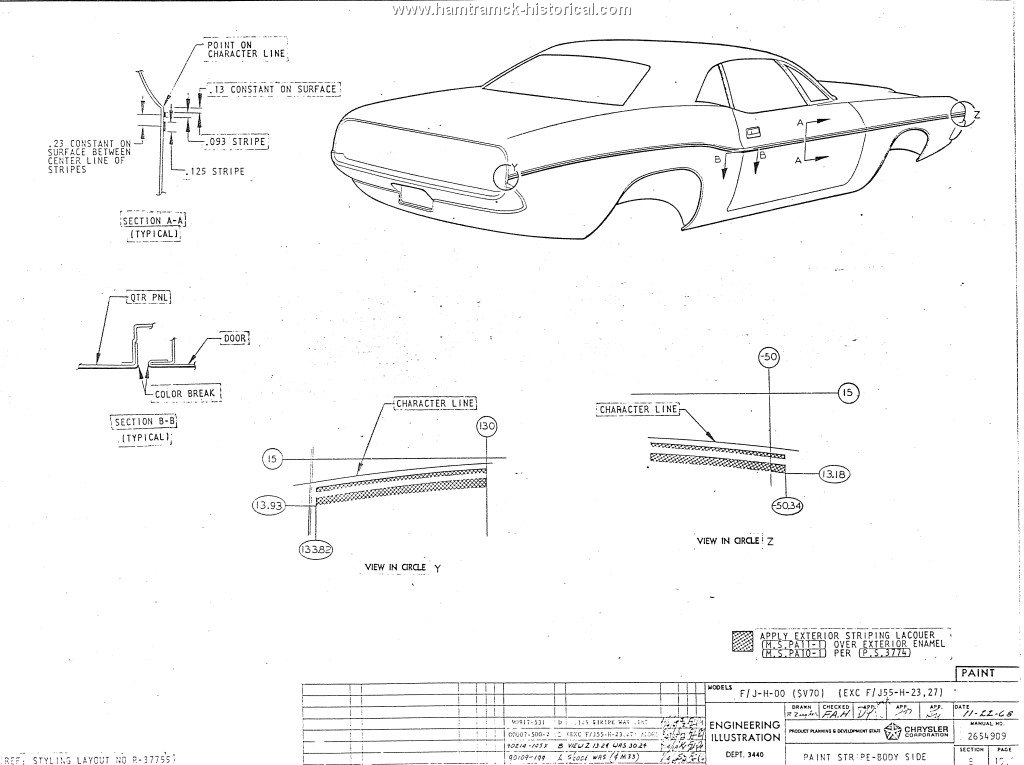
Attached picture 7663313-1970JHV7stripe.jpg
Posted By: NITROUSN

Re: Chrysler Engineering Drawings with 0 inch reference - 04/11/13 04:16 AM

Quote:

All placements are dimensioned from a 0 inch reference line.


Where do you see this O reference in the posted drawing? I see it following the body/ character line in this drawing. Not quite sure what you are asking for??.
Posted By: Alaskan_TA

Re: Chrysler Engineering Drawings with 0 inch reference - 04/11/13 04:49 AM

The zero line - draw a straight line axle center to axle center - front to back.
Posted By: 6bblgt

Re: Chrysler Engineering Drawings with 0 inch reference - 04/11/13 04:51 AM

Correct, there is no ZERO INCH line on the drawing - that's the question: Where is it?

In the Y view:
notations are 13.93" & 15" (positive) top-to-bottom from where?
and 130" & 133.82" (positive) front-to-back from where?

In the Z view:
notations are 13.18" & 15" (positive) top-to-bottom from where?
and -50" & -50.34" (negative) front-to-back from where?
Posted By: 6bblgt

Re: Chrysler Engineering Drawings with 0 inch reference - 04/11/13 04:55 AM

Quote:

The zero line - draw a straight line axle center to axle center - front to back.


Are you sure? Wouldn't that ZERO-LINE change based on factory ride height & rear springs? (an AAR's 0-line would be different from a 383 'Cuda)
Posted By: Alaskan_TA

Re: Chrysler Engineering Drawings with 0 inch reference - 04/11/13 04:56 AM

Quote:

In the Y view:
notations are 13.93" & 15" (positive) top-to-bottom from where?
and 130" & 133.82" (positive) front-to-back from where?


See above comment.

Quote:

In the Z view:
notations are 13.18" & 15" (positive) top-to-bottom from where?
and -50" & -50.34" (negative) front-to-back from where?


Front & back on the V9_ Challenger stripe drawings came from the front of the cowl top. I have not checked any other original cars against the drawings, but the one I did check was spot on.
Posted By: Alaskan_TA

Re: Chrysler Engineering Drawings with 0 inch reference - 04/11/13 05:20 AM

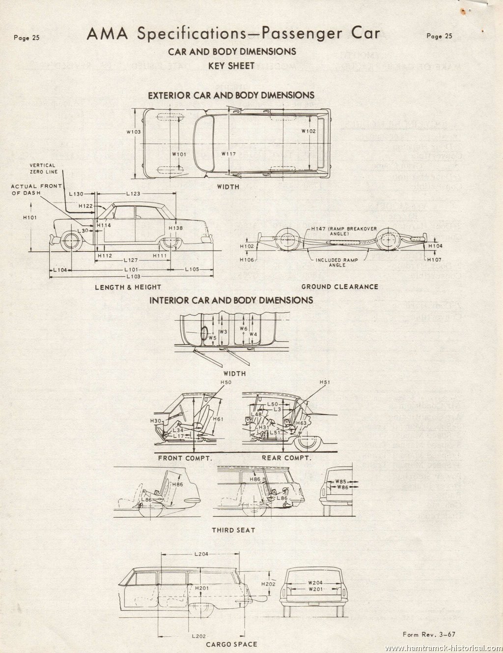
Note the reference lines at http://www.hamtramck-historical.com/ama/_1970AutomobileManufacturersAssociation-01.shtml?load_img=36

If you click on that image, it will take you to the next image with more info.
Posted By: MMC Detroit

Re: Chrysler Engineering Drawings with 0 inch reference - 04/12/13 11:00 AM

The wheel center line is usually the most convenient point to make the master horizontal datum (0) line. However,sometimes the bottom of the chassis (frame) is also used.

In general there is a vert and horz datum line. This is not always in the same location from car to car. It is want ever point is established a points of reference for a particulate model. It could be the fire wall or front when centers. The remaining grid lines are located relative to those two "zero" lines. When I get home this weekend I will see what I can find.

Generally some on this information can be found in the original master collision manuals.
Posted By: coffeeman383

Re: Chrysler Engineering Drawings with 0 inch reference - 04/12/13 01:11 PM

I was following this question on the 70 RR dust stripe thread. That drawing also referenced a zero line (vertical) and an implied horizontal zero line.

I went home and tried to determine where the “zero inch line” (on that drawing from the other thread) would be for the vertical and horizontal measurements based on my 70RR with just a fender bird (not sure if original). Here’s what I got (and I don’t like it)…

Vertical zero is NOT the pinch weld, style line, door edge, wheel centers, or obvious frame points. As near as I can tell, it’s at the left side Chrysler symbol. I based this on laying down a masking tape “dust stripe” and measuring stuff and looking for landmarks approx 13.27” down. There is nothing else obvious on the side of the car. On a frame drawing from the service manual, “0” is measured as wheel center line. Not the same zero.

Horizontally I come up with zero being the front edge of the cowl! This is pretty close to having the fake scoop edge at +75” and puts the beak of the bird at -45” (per that factory blueprint). I wish it was again the pentagon but it’s not.

The bird on my car is NOT beaked at -45” but again I don’t think it is original or didn’t matter as there was no dust stripe.

The frame drawing shows some gauge holes on frame cross members but nothing really aligns with the +75” scoop placement.

I don’t like my answer. Having two different elements for zero lines makes no sense.
Posted By: coffeeman383

Re: Chrysler Engineering Drawings with 0 inch reference - 04/12/13 01:22 PM

Quote:

Note the reference lines at http://www.hamtramck-historical.com/ama/_1970AutomobileManufacturersAssociation-01.shtml?load_img=36

If you click on that image, it will take you to the next image with more info.


On page 25 of that link it shows a drawing with "vertical zero line" labled pretty darn close to where the cowl would be. It doesn't show exactly what that line is though??? And it never shows a horizontal zero line???

The next page 26 explains all the dimensions without ever saying what the vertical line is. I think the firewall makes the most sense but not sure what exactly is flat on the firewall. maybe it really is the front cowl edge.

Attached picture 7664925-bodydimensions.jpg
Posted By: coffeeman383

Re: Chrysler Engineering Drawings with 0 inch reference - 04/13/13 05:39 PM

Posted By: MMC Detroit

Re: Chrysler Engineering Drawings with 0 inch reference - 04/14/13 02:43 PM

Quote:

The wheel center line is usually the most convenient point to make the master horizontal datum (0) line. However,sometimes the bottom of the chassis (frame) is also used.

In general there is a vert and horz datum line. This is not always in the same location from car to car. It is want ever point is established a points of reference for a particulate model. It could be the fire wall or front when centers. The remaining grid lines are located relative to those two "zero" lines. When I get home this weekend I will see what I can find.

Generally some on this information can be found in the original master collision manuals.


In the 1971 body service manual that I had handy it stated the horz "o" line as the center of the wheels.
© 2024 Moparts Forums