Moparts

The famous BALLAST RESISTOR!!!

Posted By: JL2

The famous BALLAST RESISTOR!!! - 07/22/23 04:44 PM

Simple question, with the ignition key in the run position, I have power on both terminals on the ballast resistor, is this normal? I'm fighting all kind of issues on my ignition and fuel so i'm starting with ignition.Thanks.
Posted By: TJP

Re: The famous BALLAST RESISTOR!!! - 07/22/23 05:02 PM

Originally Posted by JL2
Simple question, with the ignition key in the run position, I have power on both terminals on the ballast resistor, is this normal? I'm fighting all kind of issues on my ignition and fuel so i'm starting with ignition.Thanks.


Yes. it will also be present in the start position but the resistor is bypassed putting full voltage to the coil.
next question wink beer
Posted By: JL2

Re: The famous BALLAST RESISTOR!!! - 07/22/23 05:05 PM

How to test a voltage regulator?
Posted By: Sinitro

Re: The famous BALLAST RESISTOR!!! - 07/22/23 07:46 PM

In the START position, U should have 12V on both ballast resistor terminals.
In the RUN position, U should have 12V on the ballast resistor input terminal and 8-9V on the output terminal.

Just my $0.02... wink
Posted By: Sniper

Re: The famous BALLAST RESISTOR!!! - 07/22/23 07:50 PM

Originally Posted by JL2
How to test a voltage regulator?


That would depend on what style regulator is has, you know the first question a parts store will ask you? Year, make and model.

The FSM will cover how to test that.

Get one

https://mymopar.com/service-manuals/
Posted By: TJP

Re: The famous BALLAST RESISTOR!!! - 07/23/23 02:19 AM

Originally Posted by Sinitro
In the START position, U should have 12V on both ballast resistor terminals.
In the RUN position, U should have 12V on the ballast resistor input terminal and 8-9V on the output terminal.

Just my $0.02... wink

The 8-9V will only be when current is moving through the resistor wink
Posted By: TJP

Re: The famous BALLAST RESISTOR!!! - 07/23/23 02:24 AM

Originally Posted by Sniper
Originally Posted by JL2
How to test a voltage regulator?


That would depend on what style regulator is has, you know the first question a parts store will ask you? Year, make and model.

The FSM will cover how to test that.

Get one

https://mymopar.com/service-manuals/


most parts stores can also test the regulator for you. Year , make, model and a voltmeter will help as well. Check your grounds wink
Posted By: stumpy

Re: The famous BALLAST RESISTOR!!! - 07/23/23 02:32 AM

What kind of issues? Maybe we can help.
Posted By: Sinitro

Re: The famous BALLAST RESISTOR!!! - 07/23/23 03:03 AM

Originally Posted by TJP
Originally Posted by Sinitro
In the START position, U should have 12V on both ballast resistor terminals.
In the RUN position, U should have 12V on the ballast resistor input terminal and 8-9V on the output terminal.

Just my $0.02... wink

The 8-9V will only be when current is moving through the resistor wink


Hmmm...
U are kinda on the right track... smile
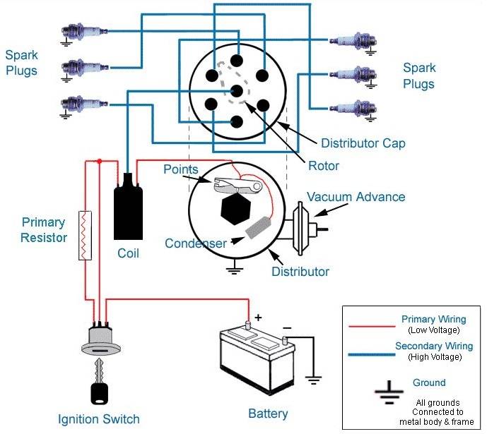
Attached file of a wiring schematic for a basic ignition system should help U better understand how things work..

Just my $0.02... wink

Attached picture ignition-system-diagram.jpg
Posted By: poorboy

Re: The famous BALLAST RESISTOR!!! - 07/23/23 03:15 AM

Since the original question was concerning an electronic ignition ballast resistor, the above diagram for a points resistor isn't correct. You need to post the diagram for an electronic 4 post resistor.

Where did the question of a voltage regulator come from? Different part for a different purpose.
Posted By: Sinitro

Re: The famous BALLAST RESISTOR!!! - 07/23/23 03:40 AM

Originally Posted by poorboy
Since the original question was concerning an electronic ignition ballast resistor, the above diagram for a points resistor isn't correct. You need to post the diagram for an electronic 4 post resistor.

Where did the question of a voltage regulator come from? Different part for a different purpose.


Forget about the voltage regulator...
Different part, part of the charging system of the alternator and battery.
Note that certain Mopars depending upon the year had an electronic ignition system using a (2) terminal ballast resistor, while others used a (4) terminal ballast resistor...
Note the (4) terminal ballast resistor was used in the early days to protect the power transistor in the ignition module, later on higher voltage capable transistors were used in the ignition module so the second resistor part of the (4) terminal ballast resistor was not required. As requested here is a basic schematic of an electronic ignition system using a (4) terminal resistor. If U have any more technical questions just PM me, no need to take up additional bandwidth.

Just my $0.02... wink


Attached picture Picture1.png
Posted By: dragon slayer

Re: The famous BALLAST RESISTOR!!! - 07/23/23 11:18 AM

I never saw a post that said electronic ignition? It is important to know wether you are working on points, original 5 pin ECU or later 4 Pin ecu system.

Second, as mentioned by earlier, you need a basic understanding of electricity also. When voltage is present, but no load being supplied. No current flow. Voltage readings will be at the Source voltage. Battery at what ever voltage it is. Only when current is flowin through the load (resistor in most DC circuits) will you see corresponding voltage drops across the load.

The Service manual really has some good trouble shooting for electrical. Good battery, Good ignition switch, good bulk head connections, etc....

Describe your symptoms that are bad, and I am sure folks can help you isolate issues to check.
Posted By: JL2

Re: The famous BALLAST RESISTOR!!! - 07/23/23 12:43 PM

This is on a 68' Barracuda 410 with Mopar orange box that I just put on. I had the MSD 6AL Digital system on . I did all of the test from info online for the MSD and it proved to be bad. Put the orange box with Mopar distributor and I'm having the same issue,,, no spark at all. Battery good, ballast resistor test good. Maybe distributor not grounded good. I'm sure it's something simple that I am overlooking.
Posted By: A727Tflite

Re: The famous BALLAST RESISTOR!!! - 07/23/23 02:18 PM

Originally Posted by JL2
This is on a 68' Barracuda 410 with Mopar orange box that I just put on. I had the MSD 6AL Digital system on . I did all of the test from info online for the MSD and it proved to be bad. Put the orange box with Mopar distributor and I'm having the same issue,,, no spark at all. Battery good, ballast resistor test good. Maybe distributor not grounded good. I'm sure it's something simple that I am overlooking.


How did you test the resistor?

Forman open or ?

Recently had a no start/no spark situation. Tested the ballast - it had voltage at the wire coming in, where the red wire for the MSD was attached. I assumed that was good enough.

I “ tested “ the ballast and it showed continuity. But the core was cracked. Replaced it and the vehicle started right up.
Looking at it again, I should just bypass the ballast.
Posted By: JL2

Re: The famous BALLAST RESISTOR!!! - 07/23/23 02:32 PM

I tested ballast for voltage with key in run position, forgot exactly the numbers but it was lower numbers coming out. I did jump the two ballast connectors for a try, but same results, no spark.
Posted By: Moparite

Re: The famous BALLAST RESISTOR!!! - 07/23/23 03:21 PM

2 or 4 post resistor? Did you check it with the terminals disconnected? If they are connected you are reading voltage threw the resistor. Ignition on one will have power and cranking the other will have power.
Posted By: Sinitro

Re: The famous BALLAST RESISTOR!!! - 07/23/23 06:32 PM

Just a suggestion... smile
Be sure and check the reluctor gap inside the Mopar electronic distributor, it should be 0.008 using a brass feeler guage...
We have had new out-of-box distributors this is set too wide, and the ignition module will not fire...

Just my $0.02... wink
Posted By: TJP

Re: The famous BALLAST RESISTOR!!! - 07/24/23 02:39 AM

Originally Posted by Sinitro
Originally Posted by TJP
Originally Posted by Sinitro
In the START position, U should have 12V on both ballast resistor terminals.
In the RUN position, U should have 12V on the ballast resistor input terminal and 8-9V on the output terminal.

Just my $0.02... wink

The 8-9V will only be when current is moving through the resistor wink


Hmmm...
U are kinda on the right track... smile
Attached file of a wiring schematic for a basic ignition system should help U better understand how things work..

Just my $0.02... wink


not sure If you were responding to me or the OP, confused shruggy beer
Posted By: JL2

Re: The famous BALLAST RESISTOR!!! - 07/24/23 11:30 AM

Thanks for all of the help my buddies. My little brother found a test for the coil that I thought I had done. Which I know I did but must have not read meter correctly. Found coil to be bad. I had an old coil hanging around and threw it on and it fired up. I’m not going to use this old coil. Y’all have any recommendations for street strip. 410, pump gas using orange box setup may put the MSD 6AL Digital box and distributor back in?
Posted By: topside

Re: The famous BALLAST RESISTOR!!! - 07/24/23 02:47 PM

If things don't have to look stock, the best coils I've used are the early '90s F150 epoxy-filled units.
Local auto parts should have them under $40 - or spend double that for MSD red paint.
They use a pigtail - also sold at auto parts stores, about $8 - and use an HEI terminal, so you'll need a matching coil wire for a few bucks more.
I fab a small mounting bracket for them from aluminum angle stock.
Best coils I've used, and can be mounted in any orientation you like.

For stock-appearing street cars, I use the restoration coils, and they work fine with the (hidden) orange boxes & OEM ballasts.
Posted By: TJP

Re: The famous BALLAST RESISTOR!!! - 07/24/23 03:48 PM

iI've had the best luck with MSD blaster II coils. I also have a new one in the box, PM if interested wink
Posted By: NachoRT74

Re: The famous BALLAST RESISTOR!!! - 07/24/23 09:33 PM

Originally Posted by Sinitro
In the START position, U should have 12V on both ballast resistor terminals.
In the RUN position, U should have 12V on the ballast resistor input terminal and 8-9V on the output terminal.

Just my $0.02... wink


50% correct.

In START you get the voltage reading reversed to the RUN position. Hence why the brake light (and oil if present) dims out while cranking. They are feeded from the RUN circuit throught the ballast.
Posted By: Sniper

Re: The famous BALLAST RESISTOR!!! - 07/24/23 09:36 PM

Originally Posted by NachoRT74
Originally Posted by Sinitro
In the START position, U should have 12V on both ballast resistor terminals.
In the RUN position, U should have 12V on the ballast resistor input terminal and 8-9V on the output terminal.

Just my $0.02... wink


50% correct.

In START you get the voltage reading reversed to the RUN position. Hence why the brake light (and oil if present) dims out while cranking. They (brake and oil light) are feeded from the RUN circuit throught the ballast.


Clarified that. Though Sinitro is correct in respect to voltage going to the coil.
© 2024 Moparts Forums