Moparts

727 valve body tear down and inspection

Posted By: B300 VanDanage

727 valve body tear down and inspection - 06/15/21 01:38 AM

Stock 727 out of a 79' B300...

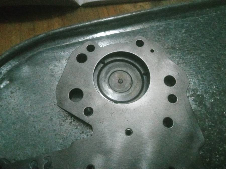
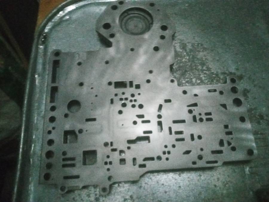
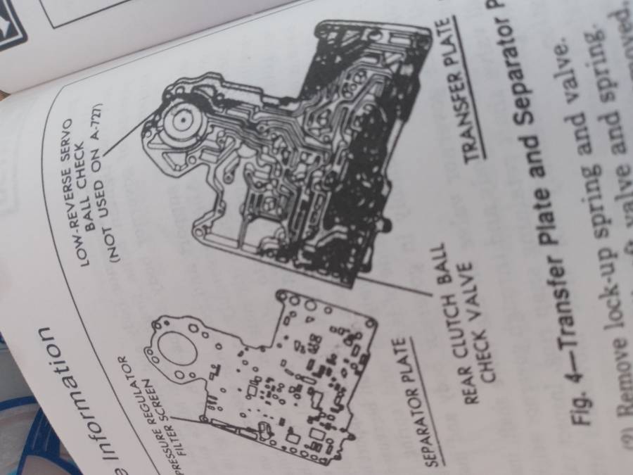
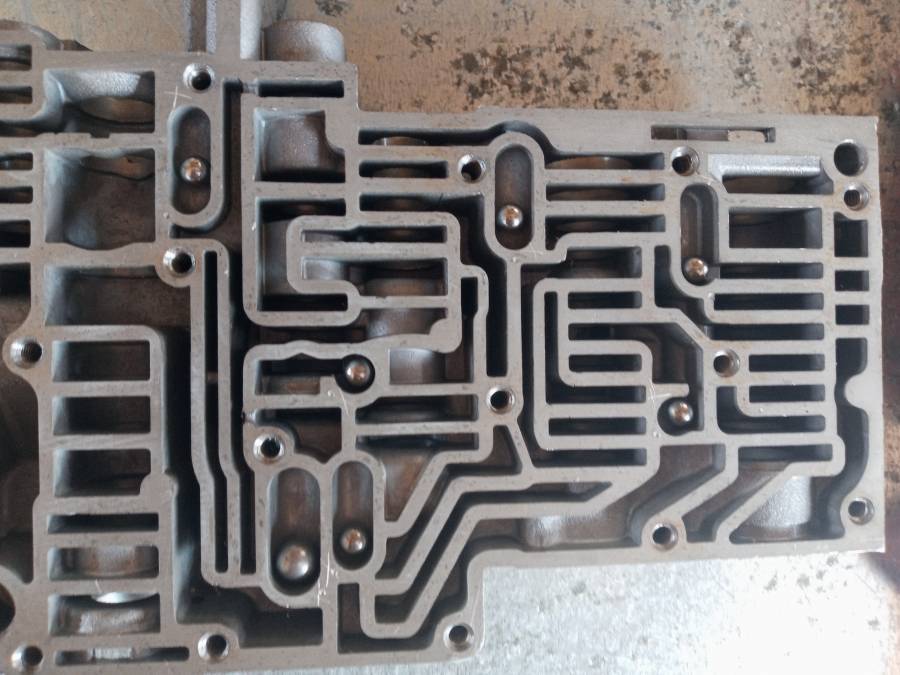
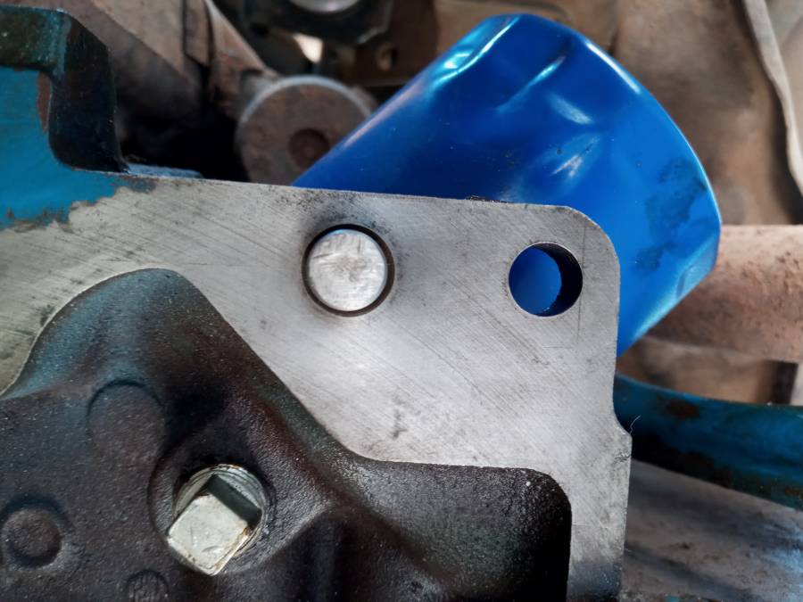
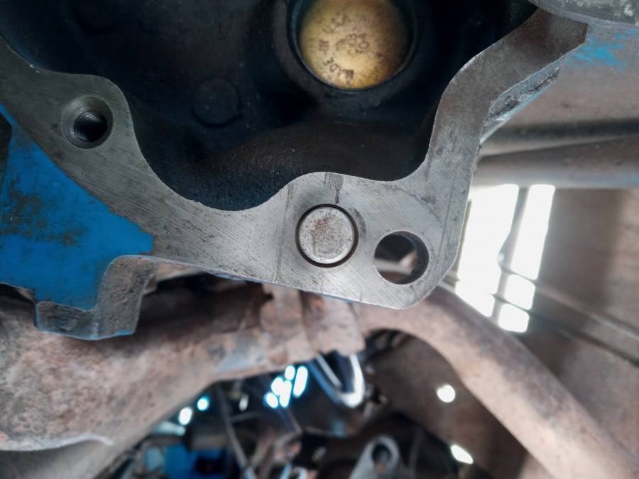
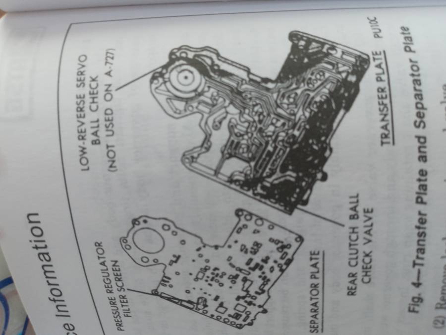
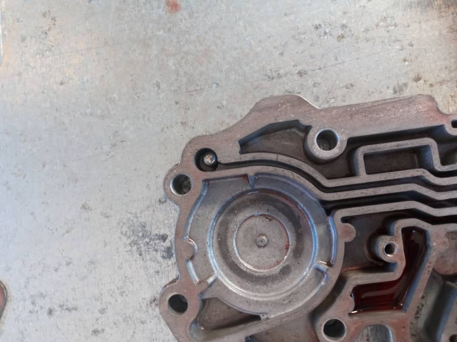
I've decide to leave the valve body for last in my rebuild and upon disassembly and using the ATSG guide as a reference I've noticed that the valve body I have uses a low reverse ball but in the book the picture shows that it's not used in a 727... So why do I have one and could that be the reason I didn't have reverse??

Attached picture 20210614_183430.jpg
Attached picture 20210614_183625.jpg
Posted By: A727Tflite

Re: 727 valve body tear down and inspection - 06/15/21 03:22 AM

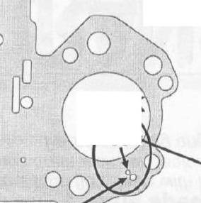
If there is just one hole above that ball, in the separator plate then you will have no manual low or reverse.
Two holes in the plate and the check ball slows reverse and manual low application.
Posted By: B300 VanDanage

Re: 727 valve body tear down and inspection - 06/15/21 03:49 AM

Originally Posted by Transman
If there is just one hole above that ball, in the separator plate then you will have no manual low or reverse.
Two holes in the plate and the check ball slows reverse and manual low application.


Mine has the one hole...
So that ball will stop the flow through that hole? Is it suppose to be there? I don't understand...
So because it's there I didn't have flow preventing reverse and low from working?
Is this the reason I didn't have reverse? Also the reason why the manual says that 727 transmissions don't use them?

Attached picture 20210614_203543.jpg
Attached picture 20210614_203531.jpg
Posted By: 4406bbl

Re: 727 valve body tear down and inspection - 06/15/21 04:20 AM

Originally Posted by B300 VanDanage
Originally Posted by Transman
If there is just one hole above that ball, in the separator plate then you will have no manual low or reverse.
Two holes in the plate and the check ball slows reverse and manual low application.


Mine has the one hole...
So that ball will stop the flow through that hole? Is it suppose to be there? I don't understand...
So because it's there I didn't have flow preventing reverse and low from working?
Is this the reason I didn't have reverse? Also the reason why the manual says that 727 transmissions don't use them?


That would stop reverse from working, I think they did that that because reverse was so harsh from higher pressure and breaking rear bands. I would leave it out, without knowing if that valve body is original, or has its original separator plate and years of castings and being a single hole vs 2 hole plate as mentioned earlier.
Posted By: A727Tflite

Re: 727 valve body tear down and inspection - 06/15/21 08:00 AM

Make sure you have the balls in the correct spot. You should have 7 balls, one large one, and 6 small. (Early 727 got 6 balls total).

That may be why you have the one in the rear servo, it may be the one that belongs to the rear clutch.

The rear servo got two balls (with two holes) to slow the application rate for reverse because customers complained of harsh reverse application.
Nothing to do with breaking the rear band.
Posted By: B300 VanDanage

Re: 727 valve body tear down and inspection - 06/15/21 03:22 PM

Originally Posted by Transman
Make sure you have the balls in the correct spot. You should have 7 balls, one large one, and 6 small. (Early 727 got 6 balls total).

That may be why you have the one in the rear servo, it may be the one that belongs to the rear clutch.

The rear servo got two balls (with two holes) to slow the application rate for reverse because customers complained of harsh reverse application.
Nothing to do with breaking the rear band.


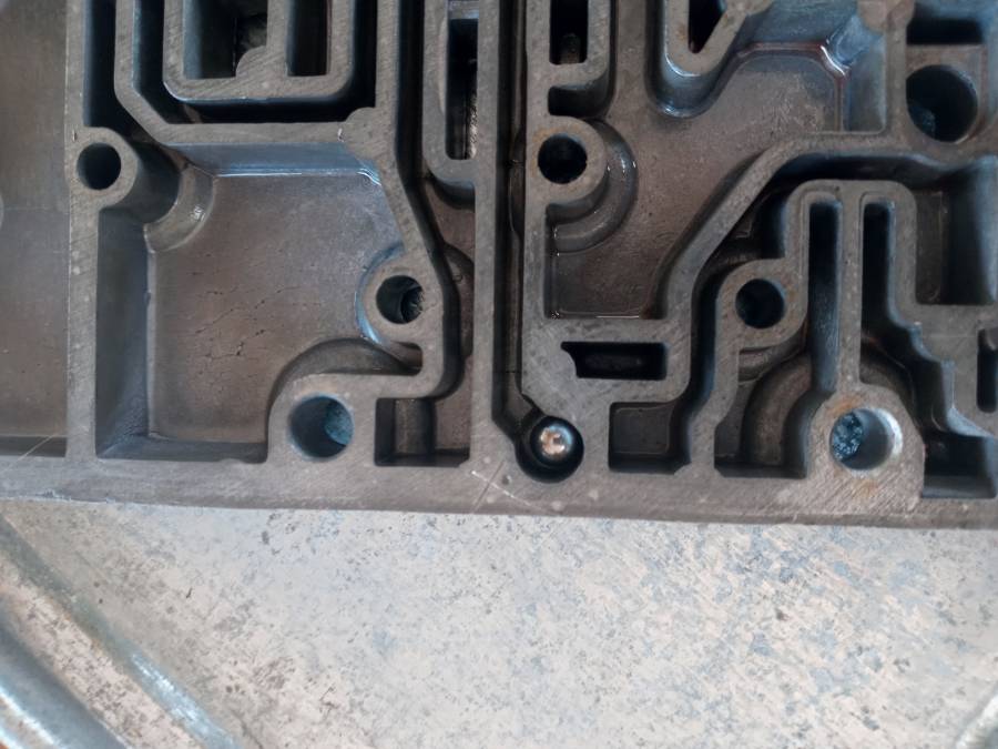
There's 7 balls in the top half and there's suppose to be one(rear clutch check valve) in the lower half of the body...
I have all my balls and all in the correct locations according to the ATSG guide.
The only ball out of place was that one that's not suppose to be in the low reverse servo.
Also, there are little x's etched into the metal where all the balls go but no x at the low reverse servo.

So this confirms it then! They put a ball where there wasn't suppose to be one!
This and the misalignment that I've mentioned in my other threads makes me wonder how they could've messed up so bad...Either way that shop is going to hear from me! Not looking forward to that.

Attached picture 20210615_082308.jpg
Attached picture 20210615_082407.jpg
Attached picture 20210615_082505.jpg
Posted By: A727Tflite

Re: 727 valve body tear down and inspection - 06/15/21 03:36 PM

Please post a pic of your valve body with the balls in place.
The lower aluminum portion is called the Transfer Plate, the sheet metal part is called the Separator Plate..

The transfer plate should only have one ball, and that’s for the rear clutch apply. You can leave that out if you want a firmer and quicker rear clutch apply.
Posted By: B300 VanDanage

Re: 727 valve body tear down and inspection - 06/15/21 04:56 PM

Originally Posted by Transman
Please post a pic of your valve body with the balls in place.
The lower aluminum portion is called the Transfer Plate, the sheet metal part is called the Separator Plate..

The transfer plate should only have one ball, and that’s for the rear clutch apply. You can leave that out if you want a firmer and quicker rear clutch apply.


I did...
Posted By: A727Tflite

Re: 727 valve body tear down and inspection - 06/15/21 05:20 PM

Originally Posted by B300 VanDanage
Originally Posted by Transman
Please post a pic of your valve body with the balls in place.
The lower aluminum portion is called the Transfer Plate, the sheet metal part is called the Separator Plate..

The transfer plate should only have one ball, and that’s for the rear clutch apply. You can leave that out if you want a firmer and quicker rear clutch apply.


I did...


Every once in a while my iPad doesn’t pop the image up, sorry, I see it now.
Posted By: B300 VanDanage

Re: 727 valve body tear down and inspection - 06/15/21 05:35 PM

Originally Posted by Transman
Originally Posted by B300 VanDanage
Originally Posted by Transman
Please post a pic of your valve body with the balls in place.
The lower aluminum portion is called the Transfer Plate, the sheet metal part is called the Separator Plate..

The transfer plate should only have one ball, and that’s for the rear clutch apply. You can leave that out if you want a firmer and quicker rear clutch apply.


I did...


Every once in a while my iPad doesn’t pop the image up, sorry, I see it now.


Haha it's cool...

So I think everything looks about right now with that extra ball out of the low reverse spot...

I'm trying to assemble everything and I don't remember which way the
Kick down valve detent goes...
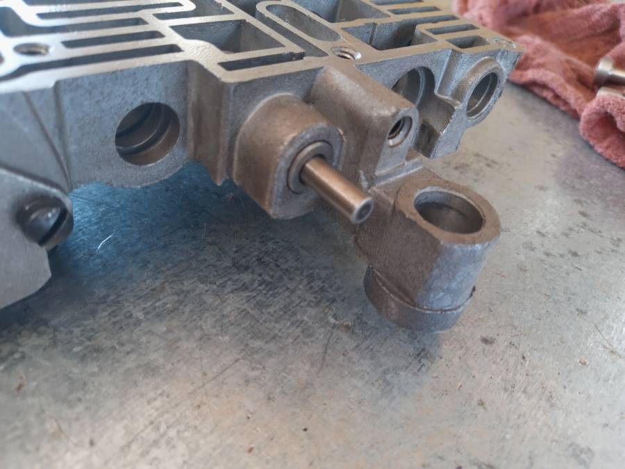
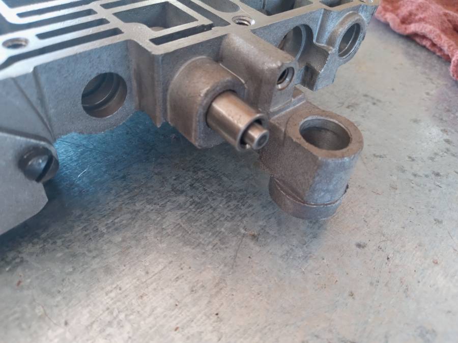
Does it sit flush to the body or protrude???

Or is it called sleeve on a plunger? Either way does the sleeve sit flush or stick out of the body?

Attached picture 20210615_102509.jpg
Attached picture 20210615_102458.jpg
Posted By: 4406bbl

Re: 727 valve body tear down and inspection - 06/15/21 05:50 PM

It sits flush, if you put it in backwards you get extremely high upshifts, like first at 50 second at 70.
Posted By: B300 VanDanage

Re: 727 valve body tear down and inspection - 06/15/21 05:57 PM

Originally Posted by 4406bbl
It sits flush, if you put it in backwards you get extremely high upshifts, like first at 50 second at 70.


I thought so but I wasn't sure and I couldn't find clear pictures of it assembled... thanks!
Posted By: B300 VanDanage

Re: 727 valve body tear down and inspection - 06/15/21 06:14 PM

Ok so...
I now have to decide if I want quicker and firmer shifts in reverse or not...
Once I do that I should have it all back together today hopefully... The tranny not the install...

It usually takes me a whole day to get the tranny in the van because I don't have the proper equipment and I'm doing it all on dirt so it makes it a little more difficult to roll heavy objects around...

I appreciate all the help I've received from everyone so far! Thank you!

Transman, you've had an answer for me in every thread I post and I appreciate that!
We've figured out why it had no reverse but still not clear about the misalignment. A bad torque converter? Maybe... I really don't think it was the flex plate but I bought a new one anyway just in case...

Hopefully this works out in the end. It's my first rebuild and honestly I'm almost glad they messed up the tranny because now I have this new knowledge about transmissions and new found confidence to actually work on them.
It wasn't as bad as I thought.
Posted By: John_Kunkel

Re: 727 valve body tear down and inspection - 06/15/21 06:21 PM

Originally Posted by Transman
If there is just one hole above that ball, in the separator plate then you will have no manual low or reverse.
Two holes in the plate and the check ball slows reverse and manual low application.


For reference, the separator plate used with the check ball.

Attached picture Sep Plate.jpg
Posted By: B300 VanDanage

Re: 727 valve body tear down and inspection - 06/15/21 06:36 PM

Originally Posted by John_Kunkel
Originally Posted by Transman
If there is just one hole above that ball, in the separator plate then you will have no manual low or reverse.
Two holes in the plate and the check ball slows reverse and manual low application.


For reference, the separator plate used with the check ball.


Cool...

Makes sense.
Those are mistakes a tranny shop should not be making! I'm suspicious because there was no x scribed in that spot and every other spot for the balls has one. Hmm...
Posted By: A727Tflite

Re: 727 valve body tear down and inspection - 06/15/21 08:13 PM

Originally Posted by B300 VanDanage
Ok so...
I now have to decide if I want quicker and firmer shifts in reverse or not...
Once I do that I should have it all back together today hopefully... The tranny not the install...

It usually takes me a whole day to get the tranny in the van because I don't have the proper equipment and I'm doing it all on dirt so it makes it a little more difficult to roll heavy objects around...

I appreciate all the help I've received from everyone so far! Thank you!

Transman, you've had an answer for me in every thread I post and I appreciate that!
We've figured out why it had no reverse but still not clear about the misalignment. A bad torque converter? Maybe... I really don't think it was the flex plate but I bought a new one anyway just in case...

Hopefully this works out in the end. It's my first rebuild and honestly I'm almost glad they messed up the tranny because now I have this new knowledge about transmissions and new found confidence to actually work on them.
It wasn't as bad as I thought.


Once the unit is built properly on the bench with correct input shaft (drivetrain end play) and the converter is installed correctly you should only have to verify that the converter is indexed properly to the flex plate. My suggestion is find the offset lug on the flexplate and put a paint mark on it and set it at 6 O’Clock by turning the crank.
Lightly lube the converter pilot and the crank pilot pocket.

Then make sure once the trans is married to the engine that you have the offset lug at 6. You should have no problem sliding the converter in to the pilot. You should have about an 1/8” gap between the converter drive lugs and the flex at this point.

Snug the bolts up finger right up until they are all in. Then torque them.
Don’t torque the first bolt then move to the rest, that can cock the converter.

I think I mentioned it before - make sure both block dowel pins are there and the holes for them in the trans case are in good shape and not elongated.

You should be good from that point on.
Posted By: B300 VanDanage

Re: 727 valve body tear down and inspection - 06/15/21 10:51 PM

Originally Posted by Transman
Originally Posted by B300 VanDanage
Ok so...
I now have to decide if I want quicker and firmer shifts in reverse or not...
Once I do that I should have it all back together today hopefully... The tranny not the install...

It usually takes me a whole day to get the tranny in the van because I don't have the proper equipment and I'm doing it all on dirt so it makes it a little more difficult to roll heavy objects around...

I appreciate all the help I've received from everyone so far! Thank you!

Transman, you've had an answer for me in every thread I post and I appreciate that!
We've figured out why it had no reverse but still not clear about the misalignment. A bad torque converter? Maybe... I really don't think it was the flex plate but I bought a new one anyway just in case...

Hopefully this works out in the end. It's my first rebuild and honestly I'm almost glad they messed up the tranny because now I have this new knowledge about transmissions and new found confidence to actually work on them.
It wasn't as bad as I thought.


Once the unit is built properly on the bench with correct input shaft (drivetrain end play) and the converter is installed correctly you should only have to verify that the converter is indexed properly to the flex plate. My suggestion is find the offset lug on the flexplate and put a paint mark on it and set it at 6 O’Clock by turning the crank.
Lightly lube the converter pilot and the crank pilot pocket.

Then make sure once the trans is married to the engine that you have the offset lug at 6. You should have no problem sliding the converter in to the pilot. You should have about an 1/8” gap between the converter drive lugs and the flex at this point.

Snug the bolts up finger right up until they are all in. Then torque them.
Don’t torque the first bolt then move to the rest, that can cock the converter.

I think I mentioned it before - make sure both block dowel pins are there and the holes for them in the trans case are in good shape and not elongated.

You should be good from that point on.

Before I get to all that there are two things that come to mind that "might" be important and just another thing the shop may have made a mistake on and that's:

Line pressure and throttle pressure adjustment...

I didn't see anything about it in the manuals I have(unless I missed it).
Posted By: moparx

Re: 727 valve body tear down and inspection - 06/16/21 03:21 PM

even though the transmission is located by two dowels, i like to take a couple pieces of all thread and make a couple of long "pilot" bolts to put in the highest, easy to get to, bolt holes.
i make a screwdriver slot in the ends with a wizz wheel to make them easy to remove.
the pilots are easier [for me] to hit the holes as they are longer than the dowels. once the transmission hits the "pilot" bolts, the dowels come easy.
remove the pilots and install the proper bolts.
just something that works for me.
beer
Posted By: B300 VanDanage

Re: 727 valve body tear down and inspection - 06/16/21 05:55 PM

Originally Posted by moparx
even though the transmission is located by two dowels, i like to take a couple pieces of all thread and make a couple of long "pilot" bolts to put in the highest, easy to get to, bolt holes.
i make a screwdriver slot in the ends with a wizz wheel to make them easy to remove.
the pilots are easier [for me] to hit the holes as they are longer than the dowels. once the transmission hits the "pilot" bolts, the dowels come easy.
remove the pilots and install the proper bolts.
just something that works for me.
beer

That's a good idea...
I think my dowels are in great condition.
There's so much space under that van I won't have problems getting it lined up...

Now as for the line and throttle pressure I'd really like to make sure they're adjusted correctly if anyone can help me out with that.
Haven't found much info on that...

Attached picture 20210616_093447.jpg
Attached picture 20210616_093546.jpg
Posted By: 4406bbl

Re: 727 valve body tear down and inspection - 06/16/21 06:26 PM

You were talking about putting a shaft kit in it, that would give you the instructions on lining up the cage to the manual valve, and how to measure the pressure regulator. The old b@m and trans go kits came with a template to set it. You could either find the instructions online or I could send you a pic of the template later.
Posted By: B300 VanDanage

Re: 727 valve body tear down and inspection - 06/16/21 11:18 PM

Originally Posted by 4406bbl
You were talking about putting a shaft kit in it, that would give you the instructions on lining up the cage to the manual valve, and how to measure the pressure regulator. The old b@m and trans go kits came with a template to set it. You could either find the instructions online or I could send you a pic of the template later.


I don't recall mentioning a shift kit in any of my threads... I'm pretty sure I won't be getting a new shift kit. I just need to make sure this one's adjusted, thanks!
Posted By: 4406bbl

Re: 727 valve body tear down and inspection - 06/17/21 02:46 AM

Originally Posted by B300 VanDanage
Originally Posted by 4406bbl
You were talking about putting a shaft kit in it, that would give you the instructions on lining up the cage to the manual valve, and how to measure the pressure regulator. The old b@m and trans go kits came with a template to set it. You could either find the instructions online or I could send you a pic of the template later.


I don't recall mentioning a shift kit in any of my threads... I'm pretty sure I won't be getting a new shift kit. I just need to make sure this one's adjusted, thanks!


OIC, I saw the firmer shifts and guess I mistook that. Tighten all the valve body screws to 35 inch pounds except the 3 holding the regulator cage, then measure 1-7/8" between the edge of the regulator valve adjusting screw, the allen head one, yr yto the edge of the manual valve, tighten the 3 screws. The pressure regulator is adjusted to 1-9/32" from the casting to the regulator spring adjusting plate. These are trans go specs, I would not turn a stock trans up more. One other thing I need to address is the rear band breaking, harsh engagement does break the band and fold over the apply strut, especially after installing a shift kit because reverse pressure is so high. In the 70s a buddy that owned an ammco trans shop said that is why they did the 2 holes and a single ball, maybe he was wrong. He also told me to drill a .060 hole in the reverse servo on plow trucks because of the constant forward reverse slam,and not use the shim shift kits had in the rear servo, to not break things with the pressure turned up. I have never worn a rear band, only broke the ears off. Anyway this guy was pretty successful, had to warranty transmissions, and did not have many failures so who knows if he was right. All I know is he sold us red clutch rebuild kits for $30, red bands for $15, and showed us how to modify the rear support and cooler feed to stop those failures.

Oh yeah, he used to call Chrysler reverse engagement "The Direct Connection" lmao.
Posted By: A727Tflite

Re: 727 valve body tear down and inspection - 06/17/21 06:33 AM

Originally Posted by 4406bbl
Originally Posted by B300 VanDanage
Originally Posted by 4406bbl
You were talking about putting a shaft kit in it, that would give you the instructions on lining up the cage to the manual valve, and how to measure the pressure regulator. The old b@m and trans go kits came with a template to set it. You could either find the instructions online or I could send you a pic of the template later.


I don't recall mentioning a shift kit in any of my threads... I'm pretty sure I won't be getting a new shift kit. I just need to make sure this one's adjusted, thanks!


OIC, I saw the firmer shifts and guess I mistook that. Tighten all the valve body screws to 35 inch pounds except the 3 holding the regulator cage, then measure 1-7/8" between the edge of the regulator valve adjusting screw, the allen head one, yr yto the edge of the manual valve, tighten the 3 screws. The pressure regulator is adjusted to 1-9/32" from the casting to the regulator spring adjusting plate. These are trans go specs, I would not turn a stock trans up more. One other thing I need to address is the rear band breaking, harsh engagement does break the band and fold over the apply strut, especially after installing a shift kit because reverse pressure is so high. In the 70s a buddy that owned an ammco trans shop said that is why they did the 2 holes and a single ball, maybe he was wrong. He also told me to drill a .060 hole in the reverse servo on plow trucks because of the constant forward reverse slam,and not use the shim shift kits had in the rear servo, to not break things with the pressure turned up. I have never worn a rear band, only broke the ears off. Anyway this guy was pretty successful, had to warranty transmissions, and did not have many failures so who knows if he was right. All I know is he sold us red clutch rebuild kits for $30, red bands for $15, and showed us how to modify the rear support and cooler feed to stop those failures.

Oh yeah, he used to call Chrysler reverse engagement "The Direct Connection" lmao.


I think the rear servo got the two check balls around 94. So for 32 years Chrysler used one ball. You think they would have needed to come up with a fix for broken bands before then if that was an issue. Like I said before, we went to the two ball from customer complaint of harsh reverse, especially in Jeep.
Posted By: B300 VanDanage

Re: 727 valve body tear down and inspection - 06/17/21 03:17 PM

Originally Posted by 4406bbl
Originally Posted by B300 VanDanage
Originally Posted by 4406bbl
You were talking about putting a shaft kit in it, that would give you the instructions on lining up the cage to the manual valve, and how to measure the pressure regulator. The old b@m and trans go kits came with a template to set it. You could either find the instructions online or I could send you a pic of the template later.


I don't recall mentioning a shift kit in any of my threads... I'm pretty sure I won't be getting a new shift kit. I just need to make sure this one's adjusted, thanks!


OIC, I saw the firmer shifts and guess I mistook that. Tighten all the valve body screws to 35 inch pounds except the 3 holding the regulator cage, then measure 1-7/8" between the edge of the regulator valve adjusting screw, the allen head one, yr yto the edge of the manual valve, tighten the 3 screws. The pressure regulator is adjusted to 1-9/32" from the casting to the regulator spring adjusting plate. These are trans go specs, I would not turn a stock trans up more. One other thing I need to address is the rear band breaking, harsh engagement does break the band and fold over the apply strut, especially after installing a shift kit because reverse pressure is so high. In the 70s a buddy that owned an ammco trans shop said that is why they did the 2 holes and a single ball, maybe he was wrong. He also told me to drill a .060 hole in the reverse servo on plow trucks because of the constant forward reverse slam,and not use the shim shift kits had in the rear servo, to not break things with the pressure turned up. I have never worn a rear band, only broke the ears off. Anyway this guy was pretty successful, had to warranty transmissions, and did not have many failures so who knows if he was right. All I know is he sold us red clutch rebuild kits for $30, red bands for $15, and showed us how to modify the rear support and cooler feed to stop those failures.

Oh yeah, he used to call Chrysler reverse engagement "The Direct Connection" lmao.


No, I was just being told I had the option and I decided to leave the rear clutch ball in for a smoother shift...
The most I'll do to that engine is replace the carb, headers and that's pretty much it. I'm just keeping it stock so no need for any fancy kits...

So yea awesome! Thanks for the info! I really don't want to overlook anything since I've found so many mistakes...
Posted By: B300 VanDanage

Re: 727 valve body tear down and inspection - 06/22/21 04:25 AM

Originally Posted by 4406bbl
Originally Posted by B300 VanDanage
Originally Posted by 4406bbl
You were talking about putting a shaft kit in it, that would give you the instructions on lining up the cage to the manual valve, and how to measure the pressure regulator. The old b@m and trans go kits came with a template to set it. You could either find the instructions online or I could send you a pic of the template later.


I don't recall mentioning a shift kit in any of my threads... I'm pretty sure I won't be getting a new shift kit. I just need to make sure this one's adjusted, thanks!


OIC, I saw the firmer shifts and guess I mistook that. Tighten all the valve body screws to 35 inch pounds except the 3 holding the regulator cage, then measure 1-7/8" between the edge of the regulator valve adjusting screw, the allen head one, yr yto the edge of the manual valve, tighten the 3 screws. The pressure regulator is adjusted to 1-9/32" from the casting to the regulator spring adjusting plate. These are trans go specs, I would not turn a stock trans up more. One other thing I need to address is the rear band breaking, harsh engagement does break the band and fold over the apply strut, especially after installing a shift kit because reverse pressure is so high. In the 70s a buddy that owned an ammco trans shop said that is why they did the 2 holes and a single ball, maybe he was wrong. He also told me to drill a .060 hole in the reverse servo on plow trucks because of the constant forward reverse slam,and not use the shim shift kits had in the rear servo, to not break things with the pressure turned up. I have never worn a rear band, only broke the ears off. Anyway this guy was pretty successful, had to warranty transmissions, and did not have many failures so who knows if he was right. All I know is he sold us red clutch rebuild kits for $30, red bands for $15, and showed us how to modify the rear support and cooler feed to stop those failures.

Oh yeah, he used to call Chrysler reverse engagement "The Direct Connection" lmao.


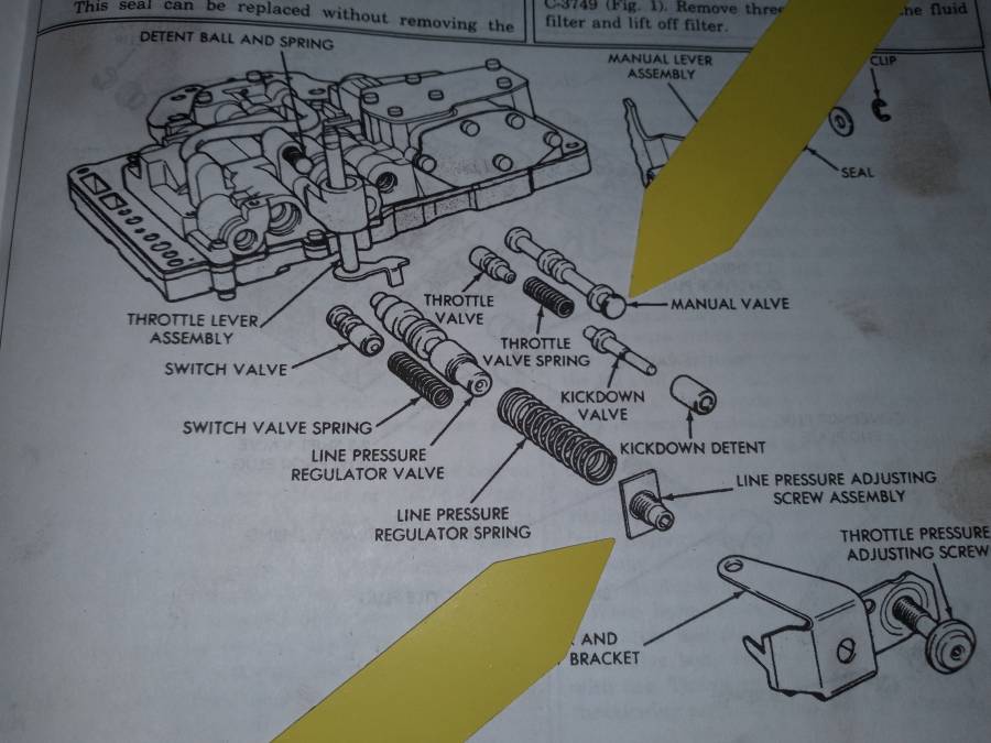
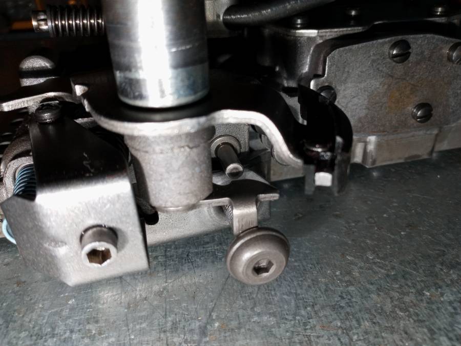
So I decided to finally get to the adjusting screws and I'm having trouble understanding your instructions... I've provided a picture for reference...

You said "measure 1-7/8" between the edge of the regulator valve adjusting screw, the allen head one, yr yto the edge of the manual valve, tighten the 3 screws. "

First off both throttle and line pressure adjusting screws are Allen head...
How am I suppose to measure from the regulator valve screw(line pressure adjusting screw) to the edge of the manual valve? I've pointed this out in the picture with yellow arrows.

Attached picture 20210621_210638.jpg
Posted By: moparx

Re: 727 valve body tear down and inspection - 06/22/21 03:55 PM

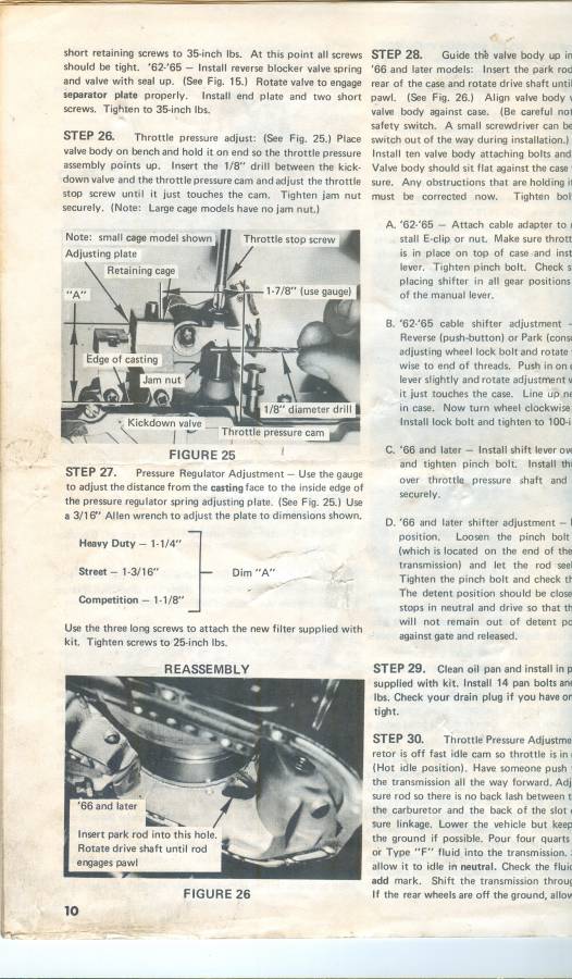
here is the picture in a B&M shift kit instruction sheet.
the 1 7/8" measurement is from the edge of the manual valve to the edge of the pressure adjustment screw.
the main reason to do this is to keep the "cage" parallel so nothing binds.
i hope this isn't too small to see.
beer

Attached picture scan0201.jpg
Posted By: 4406bbl

Re: 727 valve body tear down and inspection - 06/23/21 01:27 AM

Originally Posted by B300 VanDanage
Originally Posted by 4406bbl
Originally Posted by B300 VanDanage
Originally Posted by 4406bbl
You were talking about putting a shaft kit in it, that would give you the instructions on lining up the cage to the manual valve, and how to measure the pressure regulator. The old b@m and trans go kits came with a template to set it. You could either find the instructions online or I could send you a pic of the template later.


I don't recall mentioning a shift kit in any of my threads... I'm pretty sure I won't be getting a new shift kit. I just need to make sure this one's adjusted, thanks!


OIC, I saw the firmer shifts and guess I mistook that. Tighten all the valve body screws to 35 inch pounds except the 3 holding the regulator cage, then measure 1-7/8" between the edge of the regulator valve adjusting screw, the allen head one, yr yto the edge of the manual valve, tighten the 3 screws. The pressure regulator is adjusted to 1-9/32" from the casting to the regulator spring adjusting plate. These are trans go specs, I would not turn a stock trans up more. One other thing I need to address is the rear band breaking, harsh engagement does break the band and fold over the apply strut, especially after installing a shift kit because reverse pressure is so high. In the 70s a buddy that owned an ammco trans shop said that is why they did the 2 holes and a single ball, maybe he was wrong. He also told me to drill a .060 hole in the reverse servo on plow trucks because of the constant forward reverse slam,and not use the shim shift kits had in the rear servo, to not break things with the pressure turned up. I have never worn a rear band, only broke the ears off. Anyway this guy was pretty successful, had to warranty transmissions, and did not have many failures so who knows if he was right. All I know is he sold us red clutch rebuild kits for $30, red bands for $15, and showed us how to modify the rear support and cooler feed to stop those failures.

Oh yeah, he used to call Chrysler reverse engagement "The Direct Connection" lmao.


So I decided to finally get to the adjusting screws and I'm having trouble understanding your instructions... I've provided a picture for reference...

You said "measure 1-7/8" between the edge of the regulator valve adjusting screw, the allen head one, yr yto the edge of the manual valve, tighten the 3 screws. "

First off both throttle and line pressure adjusting screws are Allen head...
How am I suppose to measure from the regulator valve screw(line pressure adjusting screw) to the edge of the manual valve? I've pointed this out in the picture with yellow arrows.


The throttle pressure adjusting screw varied in style thru the years as you can see in the B&M instructions, and it does not measure that 1-7/8. The cage just needs to be parallel to the valve body. Slide the manual valve out and measure it is what I do.
Posted By: B300 VanDanage

Re: 727 valve body tear down and inspection - 06/23/21 04:33 AM

It took me a while of starring back and fourth from my valve body to the B&M instructions on my phone but I got it figured out...
I think I finally understand, appreciate the help so far!

I measured from the casting to the very end of the line pressure adjusting screw and it's exactly 1 7/8"'s... I'm still going to measure from the casting to the adjusting plate... According to the B&M instructions I have 3 options? I'll probably go with the heavy duty... It's stock but the converter is HD and the clutches are HD...idk...

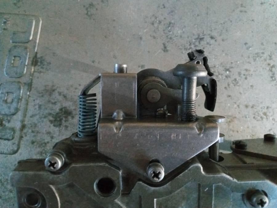
Here's a picture of the style cage and bolt I have in my 727...

The cage is a bit off in the picture because none of the screws are tight, waiting on a new torque wrench!

Attached picture 20210622_195907.jpg
Attached picture 20210622_195120.jpg
Posted By: B300 VanDanage

Re: 727 valve body tear down and inspection - 06/23/21 05:09 AM

Originally Posted by moparx
here is the picture in a B&M shift kit instruction sheet.
the 1 7/8" measurement is from the edge of the manual valve to the edge of the pressure adjustment screw.
the main reason to do this is to keep the "cage" parallel so nothing binds.
i hope this isn't too small to see.
beer


Awesome! Appreciate it... Isn't too small?... What matters is that it's focused, I can always zoom in!😁👍

As for the 3 options given in the instructions for the line pressure adjustment... That does apply to my setup correct? Since I have hd discs and hd converter I was thinking I'll be doing the Heavy Duty option. What is the difference between those adjustments anyway??
Posted By: B300 VanDanage

Re: 727 valve body tear down and inspection - 06/23/21 05:20 AM

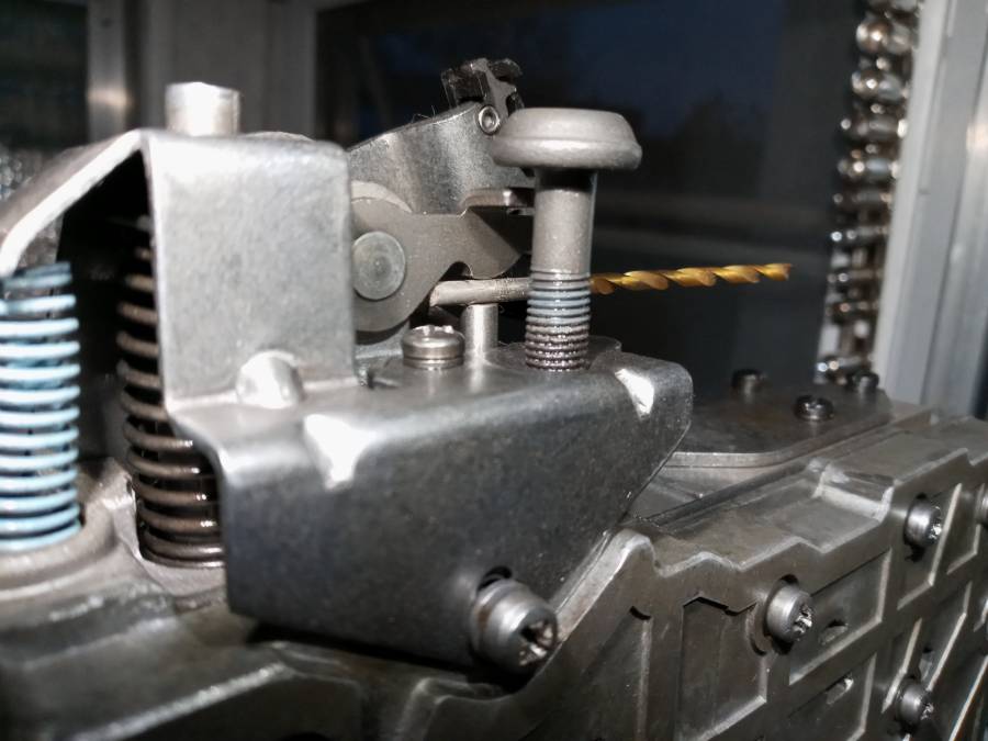
Ok so I noticed the throttle adjustment screw has some discoloration on the threads from where it was originally adjusted correctly. I measured the gap with the 1/8" bit and the throttle screw is off by at least 1/8th"!

The shop that rebuilt this made too many rookie mistakes IMO... Makes me suspicious... shake_head

Is that thread locker or just paint on those threads?

Attached picture 20210622_201210.jpg
Posted By: 4406bbl

Re: 727 valve body tear down and inspection - 06/23/21 03:23 PM

Originally Posted by B300 VanDanage
Ok so I noticed the throttle adjustment screw has some discoloration on the threads from where it was originally adjusted correctly. I measured the gap with the 1/8" bit and the throttle screw is off by at least 1/8th"!

The shop that rebuilt this made too many rookie mistakes IMO... Makes me suspicious... shake_head

Is that thread locker or just paint on those threads?


Threadlocker, they used a locknut on earlier valve bodies. I would go with the first spec I gave you for the regulator, but it is your call. Yes they made a few mistakes.
Posted By: moparx

Re: 727 valve body tear down and inspection - 06/23/21 03:29 PM

i believe that "blue" is medium strength [blue] thread locker.
beer
Posted By: B300 VanDanage

Re: 727 valve body tear down and inspection - 06/25/21 03:27 PM

Originally Posted by 4406bbl
Originally Posted by B300 VanDanage
Ok so I noticed the throttle adjustment screw has some discoloration on the threads from where it was originally adjusted correctly. I measured the gap with the 1/8" bit and the throttle screw is off by at least 1/8th"!

The shop that rebuilt this made too many rookie mistakes IMO... Makes me suspicious... shake_head

Is that thread locker or just paint on those threads?


Threadlocker, they used a locknut on earlier valve bodies. I would go with the first spec I gave you for the regulator, but it is your call. Yes they made a few mistakes.


I really don't understand the difference of the pressure adjustment...

What difference will it make setting the line pressure at 1 1/4" vs 1 9/32?
Is it that the tighter the adjustment the more "umph" it will have for shifting?
Posted By: A727Tflite

Re: 727 valve body tear down and inspection - 06/25/21 05:19 PM

Originally Posted by B300 VanDanage
Originally Posted by 4406bbl
Originally Posted by B300 VanDanage
Ok so I noticed the throttle adjustment screw has some discoloration on the threads from where it was originally adjusted correctly. I measured the gap with the 1/8" bit and the throttle screw is off by at least 1/8th"!

The shop that rebuilt this made too many rookie mistakes IMO... Makes me suspicious... shake_head

Is that thread locker or just paint on those threads?


Threadlocker, they used a locknut on earlier valve bodies. I would go with the first spec I gave you for the regulator, but it is your call. Yes they made a few mistakes.


I really don't understand the difference of the pressure adjustment...

What difference will it make setting the line pressure at 1 1/4" vs 1 9/32?
Is it that the tighter the adjustment the more "umph" it will have for shifting?


Tighter adjustment means more line pressure. That’s means a more firm clutch or band application, more holding effort. Each full turn is around 1 to 1-3/4 more psi depending on spring condition.
Posted By: B300 VanDanage

Re: 727 valve body tear down and inspection - 06/25/21 06:34 PM

W
Originally Posted by Transman
Originally Posted by B300 VanDanage
Originally Posted by 4406bbl
Originally Posted by B300 VanDanage
Ok so I noticed the throttle adjustment screw has some discoloration on the threads from where it was originally adjusted correctly. I measured the gap with the 1/8" bit and the throttle screw is off by at least 1/8th"!

The shop that rebuilt this made too many rookie mistakes IMO... Makes me suspicious... shake_head

Is that thread locker or just paint on those threads?


Threadlocker, they used a locknut on earlier valve bodies. I would go with the first spec I gave you for the regulator, but it is your call. Yes they made a few mistakes.


I really don't understand the difference of the pressure adjustment...

What difference will it make setting the line pressure at 1 1/4" vs 1 9/32?
Is it that the tighter the adjustment the more "umph" it will have for shifting?


Tighter adjustment means more line pressure. That’s means a more firm clutch or band application, more holding effort. Each full turn is around 1 to 1-3/4 more psi depending on spring condition.


Ah I see. Yeah I can visualize it now thanks.

It was apparently set at 1 9/32" and I decided on 1 1/4"... Just 1/32" closer and a tad more line pressure for the heavy duty clutches I installed. I'm happy with that...
Posted By: B300 VanDanage

Re: 727 valve body tear down and inspection - 06/25/21 06:38 PM

Originally Posted by 4406bbl
Originally Posted by B300 VanDanage
Ok so I noticed the throttle adjustment screw has some discoloration on the threads from where it was originally adjusted correctly. I measured the gap with the 1/8" bit and the throttle screw is off by at least 1/8th"!

The shop that rebuilt this made too many rookie mistakes IMO... Makes me suspicious... shake_head

Is that thread locker or just paint on those threads?


Threadlocker, they used a locknut on earlier valve bodies. I would go with the first spec I gave you for the regulator, but it is your call. Yes they made a few mistakes.


Decided on 1 1/4" only because I installed the heavy duty clutches and kick down band. I hope that's not too much for my application.
Posted By: John_Kunkel

Re: 727 valve body tear down and inspection - 06/26/21 06:50 PM

Originally Posted by Transman


Tighter adjustment means more line pressure. That’s means a more firm clutch or band application, more holding effort. Each full turn is around 1 to 1-3/4 more psi depending on spring condition.


The dimension shown in the snip from the B&M instructions is based on a different regulator spring supplied with their kit, the stiffer blue spring from the kit would yield more like 4-5 psi for each full turn.
Posted By: moparx

Re: 727 valve body tear down and inspection - 06/27/21 05:27 PM

john is correct. i should have mentioned that pic of the instruction sheet was to just show where the 1 7/8" measurement was taken, and to disregard the rest.
beer
© 2024 Moparts Forums