Moparts

Replacing ECU Wiring

Posted By: dart4forte

Replacing ECU Wiring - 11/24/19 12:17 AM

Have an intermittent short in the ECU wiring. Tracked it down to where it plugs into the ECU. Engine runs rough in drive, traced it down to the brown wire that goes to the dizzy. This is the original harness for a 74 318 so I have the 4 post ballast resistor. Looked up replacement for harness on Summitt. Can I use this harness as a replacement
Posted By: RapidRobert

Re: Replacing ECU Wiring - 11/24/19 12:31 AM

one of the reviews said he did not know why the green (5th) wire pigtail is there. It is for the 4 terminal ballast system that you have so yes it will work for you
Posted By: Sniper

Re: Replacing ECU Wiring - 11/24/19 12:32 AM

Well, you didn't post a link to the part or give the part number.

But if it has all 5 wires then yes you can use it.

BTW, Jeg's has the best prices I have found on this.
Posted By: dart4forte

Re: Replacing ECU Wiring - 11/24/19 01:34 AM

Originally Posted by dart4forte
Have an intermittent short in the ECU wiring. Tracked it down to where it plugs into the ECU. Engine runs rough in drive, traced it down to the brown wire that goes to the dizzy. This is the original harness for a 74 318 so I have the 4 post ballast resistor. Looked up replacement for harness on Summitt. Can I use this harness as a replacement


Yes, that makes sense.
Posted By: NachoRT74

Re: Replacing ECU Wiring - 11/24/19 10:27 AM

I'm not sure what you are talking about.

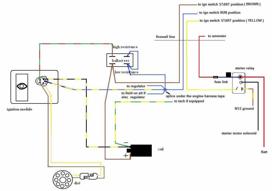
The Mopar Performance replacement pigtail for the ECU gets all the wiring required to plug the 5 pins module setup, BUT the brown wire for the ballast which is actually part of the engine harness itself.

The only wire running ORIGINALLY between Ballast and ECU is the green with red trace wire which runs straight to secondary resistor on ballast, not used on 4 pins ECU, and even less when matched with single ballast. When using double ballast setup, this wire gets it source throught the ballast with a jumper wire between ballast prongs on blue wire coming from ign switch.

The blue with yellow traces which is the keyed source for the ECU actually splices into the main splice down the harness tape just right before the regulator which spreads the RUN circuit ( blue wire ) to reg, ballast, alt field, and of course, ECU ( choke also on the run to alt field since 73 and interlock reset button since 74 ), just that when adding electronic ignition system on an originally points car, this wire uses to be spliced into the blue wire coming from ign switch at ballast or also regulator just for easier.

Brown wire runs from ign switch to ballast just to bypass it, then to +lead of coil. Doesn't go anywhere else.
Posted By: dart4forte

Re: Replacing ECU Wiring - 11/24/19 03:54 PM

Originally Posted by NachoRT74
I'm not sure what you are talking about.

The Mopar Performance replacement pigtail for the ECU gets all the wiring required to plug the 5 pins module setup, BUT the brown wire for the ballast which is actually part of the engine harness itself.

The only wire running ORIGINALLY between Ballast and ECU is the green with red trace wire which runs straight to secondary resistor on ballast, not used on 4 pins ECU, and even less when matched with single ballast. When using double ballast setup, this wire gets it source throught the ballast with a jumper wire between ballast prongs on blue wire coming from ign switch.

The blue with yellow traces which is the keyed source for the ECU actually splices into the main splice down the harness tape just right before the regulator which spreads the RUN circuit ( blue wire ) to reg, ballast, alt field, and of course, ECU ( choke also on the run to alt field since 73 and interlock reset button since 74 ), just that when adding electronic ignition system on an originally points car, this wire uses to be spliced into the blue wire coming from ign switch at ballast or also regulator just for easier.

Brown wire runs from ign switch to ballast just to bypass it, then to +lead of coil. Doesn't go anywhere else.


Ok, according to the wiring diagram this is what I currently have with the 4 prong ballast resistor

2 red wires come into the BR. Both join someplace close in the harness

There’is a green wire and it goes directly to the ECU

On the opposite side are two joined pink wires. One goes to the positive side of the coil. The other come from the ignition switch.

The dizzy connection has a gray wire and a brown with tracer. These go directly to the ECU

There’s a black with yellow tracer and it goes from the ECU to the negative side of the coil.
Posted By: Sniper

Re: Replacing ECU Wiring - 11/24/19 03:58 PM

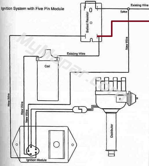
Label as appropriate for your setup

[Linked Image]
Posted By: NachoRT74

Re: Replacing ECU Wiring - 11/24/19 07:15 PM

the posted wiring got an existing wire missed ( in brown on the edited version )

Attached picture Ignition_System_5pin.jpg
Posted By: NachoRT74

Re: Replacing ECU Wiring - 11/24/19 07:25 PM

This could be more correct ( colors included ) Just not included the interlock reset system for 74 which also gets a power source from the blue wire splice ( and a diff starter relay yellow wire route )


Attached picture FACTORY IGN DIAGRAM1.jpg
© 2024 Moparts Forums