Now it was time to see how well all the cuts lined up as everything went back together. It is when you really hope you laid everything out correctly and didn't screw up...
In a span of about 8 weeks you almost have 1/4 of a car built. There are more pics to come later. I do need some feedback on naming this thing. I originally dubbed it "Time Traveler" as a play on words of E/T vs. 40 years of something that looks like a time capsule. Any thoughts anyone?
The new passenger side trunk floor pan tied into the new rear frame rails. Pic is from underneath. Here's where you try to make it look like the factory installed it.
Last one for now. This is the beginning of the new b pillar supports at the back of the roof. These used to be maybe 4" tall, back when the wheel well was in the stock location. Now its more like 10" or so.
I have made a small amount of progress but have only a couple pics to show. I managed to pick up a 65 A-100 straight axle and decided to widen the front frame rails out to the centerline spring pad dimension of 35 5/8". I used all new 2x3 tubing from the front bumper to just inside the front of the leaf spring perches. I also managed to pick-up a pair of Anson 3 1/2" aluminum slots which will keep the offset from the wider straight axle front end very similar to what the original track width on the front was with the K frame and control arms. I just broke ground for a new shop, so making any progress soon is doubtful.
The new 2x3 frame rail in the center of the car has a dimension of 51 1/2" from the leaf spring hanger to the 3.2 degree angle. The new front rail will be 54" and will be installed 5 1/2" below the bottom of the frame at the existing radiator support mount. This is where a digital level becomes a very handy tool to have.
When finished the 2 rails pictured above will be in line and have an angle of 3.2 degrees up to attach to the bottom of the frame at the radiator support. I will be installing new floor pans so as to not have to repair the removal of all of the factory spot welds at the front frame and torsion bar cross-member.
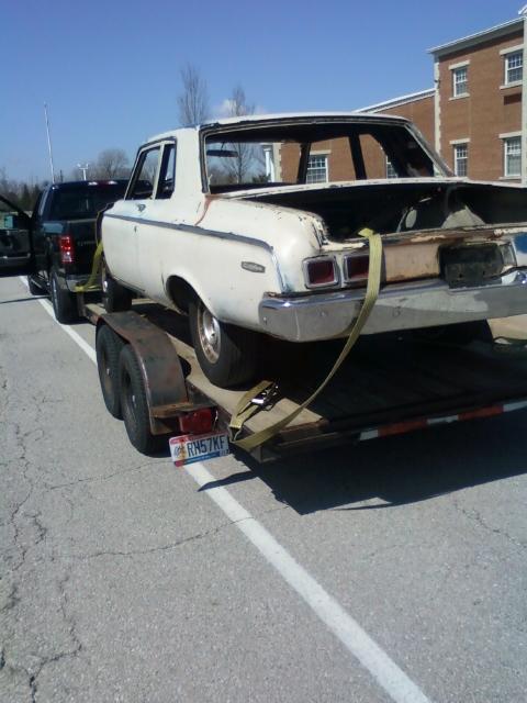
I know it has been a while since I have followed up on this but that is why they are called projects. I've managed to get some trim holes welded up and finished fabbing up a trunk floor panel with new bead rolls to align with the existing ones. Thanks to finding a parts car in New York I have all the front sheet metal I need to get back into this thing pretty hard again. I also managed to score a really nice non dash pad dash frame.
I picked up this period correct Ansen blow proof bell housing and an old school Hurst Super comp shifter. I'm looking for AWB fiberglass front fenders if anyone has a pair they want to sell. If not I guess I'll modify the steel fenders I have. Also looking for a fiberglass hood and front bumper. I finished removing the torsion bar cross member and started fitting the new front floor pans. If anyone has a drivers side floor front replacement panel left over from a project let me know. I also need a 4 speed hump used or new if anyone has one to sell. Build season is back now that the daily driver is put away in storage.
You know the deal...there is always rust damage behind what you can see. Fortunately I'm not reinstalling any of the heater box equipment so this opening can be deleted.
I use everything from a small pair of pliers to small hammers and dollies, sometimes even clamp vice grips and 2x4's. Whatever it takes to bend it however you need. Small radius'd lips like these can be a pain sometimes.
All that's left to do now is line it up and weld it in. I prefer to weld from the back thru the existing spot weld hole. It's not quite the same appearance as factory but 9 out of 10 will never see you replaced the panel.
Originally I removed the entire fire wall and all of the interior cowl area. The interior cowl under the wipers over to where it tied into the firewall was rusted pretty bad. I had planned to set this up with about a 12" engine setback and thought better of it. I put the original firewall back in but removed everything that wasn't needed. I may make a tray with a drain tube to catch any water from the cowl vents. I haven't decided whether or not to eliminate them. It's most likely easier to eliminate them too.
Yeah if it still has the louvers in the cowl it'd be easier to get rid of them than to patch the underside in to keep the floor dry. I wish I could leave mine as is but pretty sure it's going to be impound time if I get caught on the street without wipers here.
Chasing bears through the woods drunk with a dull hatchet is strongly not advised
I have managed to get a little further along over the past couple weeks. I started by installing the RH frame rail from the rear front spring hanger inside the rail forward to the c/l of the kick at the base of the firewall. These rails are installed flush at the bottom of the rear rail and ran level with the rockers.
Next I installed the LH frame rail. I determined dimensions on these rails to be 52" long from the rear to where the front rail kicks up at the firewall. I ended up adding an additional wood brace to the so called frame jig to establish and carry the new rails. I also double checked both new rails for plumb left to right where they kick up below the firewall.
I began mocking up the front frame rails and determined the angle of the new rails to be 2.3 degrees. 2.3 is too small of an increment to split for a miter joint so the rails installed at the center of the car are cut square and the new front rails are cut at 2.3 degrees. I am only mocking everything up right now as I'm trying to look eight steps ahead and see what I can do now that will help later. I made the 2x3 cross brace to cap both front rails at the front. After confirming the distance of 35 3/4" for the locater pins in the leaf springs on the straight axle the front frame rails are installed at 35 7/8" c/l dimension. This is actually about 2" wider than the factory rails were installed.
You find you'll have to check and double check everything you do to assure everything stays square...plumb and level. After pulling angle dimensions on the frame at the new front sections to check square they were about 1/32" off. Not enough to worry about on a 64 13/16" length. Nice thing is if you ever have to use any of these points at the frame kick or the front to square something up they are dead on square. I need to find a good supplier to source the leaf springs from...all of the ones that Speedway has have too long of a dimension from the locater pin to the front spring eye.
I ordered the leaf springs today. I had a guy with one of these cars tell me a while back to use trailer springs. I found a set of 26" springs with a 13" eye dimension. They already have urethane bushings and the assembly bolts come with greasable zerk fittings. I had asked a while back if anyone knew a reason not to use the leaf spring sliders on the rear of the springs rather than shackles. I've never heard anything...I guess as of now I still am planning on using the sliders.
So here is a picture of the front suspension mock up. This is a 12" forward relocation from stock of an A-100 van axle. With this design as indicated in the photo's there is a 7.5 degree lay back at the kingpins. There's really no way to know how this will react once everything is loaded with weight. I think the only thing I'm going to do different than what is pictured is to make the slider bracket at the rear so it can have shims installed between it and the frame rail that would bolt in thru a bracket welded to the frame. If ride height is an issue I can also use a tapered spacer between the springs and the straight axle at a later time. So far I'm happy with how easy this installed and with using the greasable bolts at the front and bearings at the sliders it should work well.
A couple more of the drivers side. I also ordered all of the new brake components for the 10" x 2 1/2" front drums for the A-100 Van axle. I single sourced everything thru www.partsgeek.com except the bearing cover caps on the hubs. The other pictures are of the miter at the front frame rails before they were welded and the RF box tube pad to carry the roll cage bar at the RF corner. This tubing was tied in to the side of the frame rail and then installed recessed into the inside of the rocker panels where they were plunge cut. Being 3" wide it gives me a little wiggle room later for the roll cage bar placement.
I used that leaf spring slider on the 69 Dart for a couple summers now with zero issues on the rear. Never seen or heard of anyone using it here and was just looking for some input. As for the other thing we talked about...I'm going to keep a lid on that until I pull the trigger...IF I pull the trigger... I mapped out an area on the front rails near where the front hangers for the springs are for a bar to tie in from the frame back to the roll cage. This will give me a good point for the shock bracket at the top. I did a few small modifications to the front spring hangers tonight and will post pics once I get them loaded Thursday.
Here are a few pics of the modified front spring hangers. Rather than just two tabs that stuck down I added a piece to set against the bottom of the frame and a second one to wrap down around the front of the bracket. This keeps them solid left to right and increases the available area to weld them in. On to the next task...floorboards...tunnel and firewall...
I had a couple nice days outside so I gathered up the fenders...doors...hood and bumper parts for the front end from storage. I spent most of the day yesterday stripping undercoating from the fenders. I temporarily pinned the original passenger side door on and checked all the gaps. Everything still fits well. I was kind of worried that maybe some of the integrity had been sacrificed with everything that has been modified. I don't see any issues. I marked where the leading edge of the fender needs to align and removed the door.
The fenders I have are an accident that's already happened on numerous occasions. They were only good for what I'm using them for. I hung the passenger fender and dimensioned for the drivers side door and hung the drivers side fender. I sat the hood on and made sure everything seems square. Then came the only actual fun. I used the laser and located a level line and a center line for the modified wheelbase. Relocation will be 10" forward. I installed tape on the lines that will need to be cut. The area painted in black will need to be removed. Notice how well the leading edge of the cut line aligns with the original corner of the front fender above the bumper. You can achieve this by measuring 10" forward on a level line from the wheel well and making that your cut line.
Now you can cut... Throw away the unused piece (I'm lying..don't throw away anything that has a radius or bend in it) Then tack whats left back together...
I everything works out you should end up with a dimension of about 10 1/8" of opening that will get new metal...Position the wheel opening tin and support it so its sitting where it would when finished and begin tacking it back into place. Now it starting to look like something...
Then it was on to welding up the trim holes and the antenna hole. Not as much fun...but it needs done never the less... I think I can pillage the 63 330 I just got for parts for a piece of metal to weld into the front fenders...
It worked! The 63 330 gave it's life today...as if it wasn't dead before. I sectioned an area out of the doors large enough to do the patch panels for the fenders on both sides. When I cut the back door a 3/8"-7/16" craftsman wrench fell out... I glanced down after shutting the grinder off and saw the blade was broke in half... Dumb luck I caught it before it got painful... Then I got to thinking... What would happen if I cut a section out of the rockers to finish off the bottoms of the fenders... It's worth a shot anyway...
I don't know what the #$%^!@#$ they used for undercoating inside the doors but holy crap was it ever a bear to get off I held the patch panel in on the outside of the fender and traced what I needed for a filler...cut it and installed it...No binding no pressure it just fell right into place... All but one small area that I had to trim with the tiny Dremel wheel... I did manage to clean up the passenger door today and got lucky as it was still pretty solid...
As for using the rocker to fix the fender... All of the mounting reinforcement on the bottom 8" or so has been removed thanks to mother nature. I did manage to steal a small amount out of the bottom of the 63 330 fender that if nothing else will give me a pattern to duplicate... As for the rocker skin...see for yourself...I think I can make something work...
Amend all earlier posts in this referring to the straight axle as an A-100. I found out today it's from an econoline van and not an A-100. I still can't figure out why everyone was narrowing the I beam axles to make them work. The two are very similar and there is no reason to narrow them... Outside of drum flange on the Ford axle is 62" wide with a center line spring perch dimension of 35 5/8". The same dimension on the A100 axle is 63 1/4" with a center line spring dimension of 35 3/4". I managed to get all of the layout for the drivers side fender done last evening also. I'm not going to cut anything there yet until I see if I can find another inner fender support local as the bottom of it is much worse than the passenger side was.
I made some progress with the floors and the tunnel. The original tunnel in this car was hacked to pieces along with the original torsion bar cross member due to an A body transmission install in a B Body. Moving the rear floors forward the 19" dimension makes them much higher at the front of the rear section than they were from the factory. I added metal at the sides of the new tunnel then added square nuts welded under the floors to make the tunnel removable. Passenger side is finished including the transition to the tunnel. Drivers side will be next along with some firewall repairs from previous A body pedal installation. I need to tie in the firewall and floor repairs at the same time to integrate the new bracket from the frame for the clutch equalizer bar with provisions from it to install a support for the universal on the steering column base for the relocated steering box.
I managed to complete one monster pita portion last night. Top picture is of the original 65 opening for the steering column at the base of the firewall. Note the butchered area above the original clutch rod opening. The opening is large from the factory for the steering column to allow the cable shift column to fit thru the firewall. I replaced everything with a section of firewall from the 63 330. This repairs the damage and allows me to use the base plate and tube from the 63 manual column. Although that column was a 3 on the tree column I will remove all the extra hardware so its just a floor shift manual column in the end. Clutch rod hole is all fixed along with an area of rust that showed up once I removed the bracing for the inner fender well. One more little hurdle cleared... Only a thousand more to go...
I had ordered a new drivers side floor pan from Kramer's a few weeks back. It showed up and I was kind of putting it off till the firewall was all tied in. I managed to get it all mocked up and trimmed to fit enough that the floors and firewall are all tied together where they are going to be staying. I mocked up the pedal assembly and added a piece of metal to the clutch pivot to tie it into the frame.
It won't matter now but I do need to know if the length of the big block Z bar is the same as the small block one I'm currently using. I sat an old blow-proof bell housing in and used the pivot that was on the 318 poly bell housing. Everything is level and the clutch rod when going thru its travel doesn't touch or rub anywhere. It seems centered in the hole vertically. Ultimately this is what I'll use to locate the engine and transmission mounts since I have to fab everything anyway. Just one more small piece that's 1/2 done... I added an extra brace back to the firewall to make sure there is no movement left to right at the pivot. I really wanted to get started tying in the 2 support bars on the front frame but I haven't been able to locate a set of fender well headers for a big block.
If you remember the rust repairs to the RH side of the firewall from the earlier posts than you'll recognize these. You know how things change and always seem to evolve? Case and point was this area which I thought was finished and then something else required it to be modified. Below are the modifications made. The reason for these will surface in the near future...
Really enjoying your updates and continue to marvel at your skills. Keep them coming please!
As an aside, I agree with your comments on not needing to narrow an A100 or Econoline axle. I've an Econoline front axle under my 61 A body. The conversion was done in the late 60's and has proven very workable at stock width. B body width would fit it even better.
Thx... I got my Ansen Blowproof Bellhousing back. I sent it out and had it jigged and re-drilled to accept an A833. (Pic is from before I sent it out) I picked up a correct 65 bell housing pivot and now need to begin to mock-up the engine and transmission. I'm using the Z-bar placement as the one spot that everything else will need to revolve around. It's going to be a little while before I have anything concrete as now I have to incorporate the engine-trans with the headers and front cage bar placement while integrating the steering shaft and box placement... I still need to find a set of used RB fenderwell headers. A,B,E Early B I don't really care... If something doesn't turn up soon I guess I'll have to order new...
I bit the bullit and ordered a new set of Hooker fenderwell headers today... Borrowed a 4 speed trans last night...so if everything goes right I will be mocking a few things up...
I managed to do a few more things that I haven't documented. I added two small bars (about 28") to extend the rockers forward with a 60 degree angle and tying back into the front frame rails right where the rear leaf spring slider is located. That was really the last two bars needed before removing the car from the jig. Managed to get the drivers side fender cut...relocated and tied back together. Once the fender and bars were completed I installed all the suspension.
I managed to scrounge up a set of 15x8 rear slots and a set of 31x9" slicks. Had the front runners and slicks mounted up with tubes to be able to roll it around again. Front wheels are 3 1/2" Anson slots. The rears are about 5/8" from the leaf spring on the inside. Maybe a 1/2" from the inside of the 1/4 panel lip.
With the front and rear axle's and leaf springs all installed it was ready to be removed from the jig. Outside it went rolling for the first time in about 3 years... I'm going to add some weight to let any spring settling occur and revisit what all the ride heights should be. Depending on the amount of spring sag I may need to modify a few things but for a first attempt at this I'm happy with where it ended up just using math to set everything up.
There's a good deal of satisfaction in having this rolling again. I put in it the box trailer for now and get to put the 70 back in the garage to do a few things to it before summer comes. It's been a bit of a journey from the first picture of when I got it till now...Took a little longer than I'd have liked too...
So after starting back to work on this about a month or so ago I have finally gotten around to downloading some pictures...
I started with trying to get motor and transmission mounts in the car so I could start mapping out locations for steering and everything else it was lacking...
I am using a 63 Ansen Bell housing modified to accept an A-833 4 speed transmission and all of the clutch linkage parts from a 63 330 I had parted out....
I really needed to make everything hook up and work around placing the existing equalizer bar in the correct location as I wanted to use all the clutch pedals and hardware I had without modifications...
Is it correct??? I don't know but everything works around it and turned out pretty good in the end...
I did have the shorten the equalizer bar 3/4" to locate the drivers side header away from the new...lower than stock frame rails. In the end it centered the motor up a little more and made both headers fit better...
I started out using one of the plastic blocks in the beginning and ended up switching to factory stuff to dummy everything up...
With the motor positioned where it needed to be I fabbed up the transmission mount and installed a limiter to keep the engine from ever moving toward the rear...
Installed the new transmission crossmember and mount and verified the equalizer bar was still correct...
With the motor and trans permanently located I started working on the steering box and column...
The column was a 3 speed manual one from the 63 330...It is now modified and cut down to fit and will appear to be a floor shift column when finished...
Here's where the heartburn is going to set in some of you as I used a gm manual steering box for this deal...
Much better fit than utilizing a manual Mopar box that just doesn't fit worth a crap...I can get a new one for 225.00 and can utilize an in stock 3/4" universal joint to complete the connection...
While I was waiting for tubing for the drag link and steering link to come in I moved on to completing other areas...
I installed both doors along with the vent windows and the glass and regulators...Installed the stainless glass channels for the H/T weather seals to be able to locate the position of the 1/4 windows...
I cut the original aluminum 1/4 window regulators in half and tapped them for new mounting holes to retain the factory connections to the 1/4 window glass.
No room for window cranks as there is nowhere for the glass to go anyway...
With both 1/4 windows installed I started working on the interior trim and the placement of a rear firewall....
This is not being built as an original car in any way....Its more like something someone would have put together a few years later and did not do what was done on any of the other cars...
I utilized the factory metal panels from the original door panels at the tops of the doors and the 1/4 windows and they installed in the factory screw holes... Everything else is homemade...
I made patterns for the doors and below the 1/4 windows and then transferred those to .050 aluminum...The rear firewall is also built from the .050 material...
After many paper patterns and tons of measurements this is what I ended up with...
The one thing some of you may notice about the metal panels for the doors and the 1/4 windows is that they don't have any of the extra holes in them...
All were welded up and then primed and painted leaving only the installation holes that were required...
New aluminum kick panels were also made along with the new dash panel...
This thing will be bare bones and does not utilize any of the factory instrument panel and very little factory wiring harness...
With the tinwork completed it was removed so the roll cage installation could be completed...
As it is I can cut the tin to fit once the cage is installed and do not have to try to fabricate the large pieces around a cage that was already in place...
I am only installing a 6 point cage at this time as I have no idea if this will ever actually be raced...
Main hoop bar with two bars going to rear tight to the top back edge of the package tray and then 2 bars from the cross bar in the main hoop down the floor mounts at an angle...
An additional bar is being installed behind the dash frame with 2 bars running to the front cage mounts on the floor and then two bars running forward to the firewall with steel plates...
Front bars were then installed from the firewall plates to the frame rails...I made these bars removable not knowing how easy it may or may not be to remove the fenderwell headers...
There has been some more progress in other areas but it seems I have been lacking with taking progress pictures...
More updates will come at some time in the future...
On a side note I have just installed my 3rd 10# spool of welding wire since beginning this project...
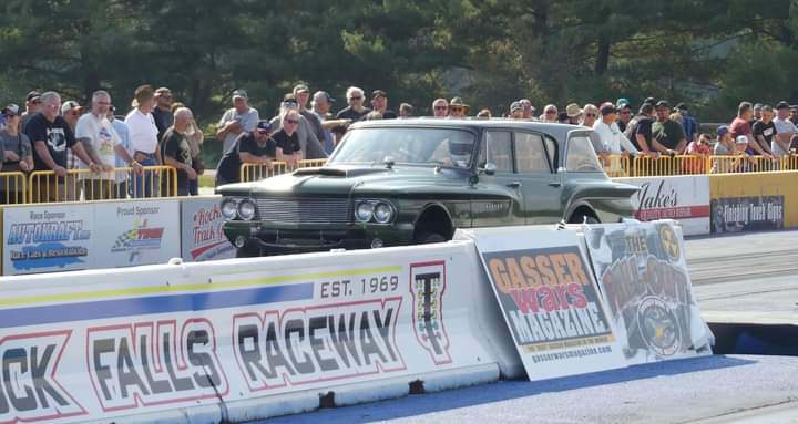
'63 Dodge 330 11.19 @ 121 mph Pump gas, n/a, through the mufflers on street tires with 3.54's. 3,600 lbs. 10.01 @ 133mph with a 250 shot of nitrous an a splash of race gas. 1.36 60 ft. 3,700 lbs.
Really enjoyed watching your fabrication, metalwork/rust repair, very nice!
Where you lost me is when you tossed the stock sub-frame and crossmembers. I don't recall any of the eras Mopar AWB cars being built this way. I hope your motor plate is beefy enough since its farther to your fabricated frame rails.
The factory even had a manual showing how to build one! Your car reminds more like the Mercury Comets that came along in I think 1966.
Did you do the engine turning on those panels yourself?
DynoDave Walter P. Chrysler Club - Great Lakes Region Member # 12304 1970 Plymouth Duster 1972 Dodge Charger Rallye https://wichargerguy.proboards.com/ 1977 Chrysler Cordoba
Nice work! Makes you dizzy... There's something to look forward to.
Nice collection of vintage parts. Love the blue sparkle steering wheel.
DynoDave Walter P. Chrysler Club - Great Lakes Region Member # 12304 1970 Plymouth Duster 1972 Dodge Charger Rallye https://wichargerguy.proboards.com/ 1977 Chrysler Cordoba
[img]http://i.imgur.com/boeexFms.jpg[/img] 31 Plymouth Coupe, 392 Hemi, T56 magnum RS23J71 RS27J77 RP23J71 RO23J71 WM21J8A I don't regret the things I've done. I only regret the things I didn't do. "Wise men talk because they have something to say; fools because they have to say something. ~ Plato"
Time to start figuring out this whole flip nose frontend deal in all steel...
What a monster PITA...
So it needs to slide forward 4 1/4" to allow for the fenders to not hit the doors while rotating up...
This means the hood would have to have the hole for the carbs cut back 4' farther than normally needed...
That's a deal breaker as that is removing all of the back of the hood behind the carbs...
When it is closed the whole top of the cowl would be visible...
Using some 3/4" tubing (steering shaft) that has a 1/2" inside hole and some 1/2" round stock I came up with this deal...
It allows the fenders to close and have an area to land on and then slides the fenders back into place so they fit as good as I could get them to fit...
The bottoms also need something to secure them so round bar was added there and a hole drilled into the end of the rockers...
I started with the drivers side and got all the bugs worked out before moving to the passenger side...
With no car here to work on it was back to finishing a lot of small parts...
I picked up this Tunnel Ram at Carlisle in July...
It is a Weiand but someone spent a bunch of time cutting all the extra aluminum out of it...
It needed some of the extra cast cleaned off of it and then blasted...
Sure did end up looking a lot different than one that is not modified...
Any chance you could post up the weight difference between the two? I'd be curious to know what all that work was worth beyond just doing it for looks.
This is a totally cool project. Are you going to add some decals and/or lettering so it looks like a vintage race car, or just leave it the two colors?
[img]http://i.imgur.com/boeexFms.jpg[/img] 31 Plymouth Coupe, 392 Hemi, T56 magnum RS23J71 RS27J77 RP23J71 RO23J71 WM21J8A I don't regret the things I've done. I only regret the things I didn't do. "Wise men talk because they have something to say; fools because they have to say something. ~ Plato"
There was enough time left at the end of the day to hang the front and rear bumpers...
The front end flips forward much easier with the bumper installed...
I hadn't said anything about this before but I did manage to work out the details of how to incorporate the front spoiler and make sure it clears everything...
OWNER OF EVERYTHING FROM 1956 300 B,IMPERIAL,NEW YORKER HEMIS,AND NEW HEMI TRUCKS.....5TH GENRAMS.COM... 1969/70 ROADRUNNERS ,DARTS/CORONETS, NORTHEAST HEMI OWNERS ASSOCIATION.....WWW.PHANTASMCUDAS.COM....MOPAR FAMILY FOR 50 YEARS AND STILL GOING!MOPAR OWNER COAST TO COAST!!!!
Love the engine turned interior panels. Hopefully it doesn't wind up being too noisy inside, but it's not the type of car one would spend hours in at a time anyways.
If that were mine I'd be real tempted to put blue gasser window tint on the windows.