Moparts

Surge Tank Implementation

Posted By: Blucuda413

Surge Tank Implementation - 04/23/18 09:08 PM

I'm planning to use a surge tank in conjunction with my mechanical injection. I'm using a small tank up front fed through a Holley float bowl. I've got 150 needle and seat in the bowl which is fed by a quality elec pump from the rear tank. My question is does there need to be a pressure regulator between the pump and the fuel bowl? In all the diagrams I've seen there is never a regulator shown, do I need one??
Posted By: Cab_Burge

Re: Surge Tank Implementation - 04/24/18 12:48 AM

How much pressure will your pump make?
If above 9.5 lbs. I would use a good regulator now up twocents
BTW, I have never use that large size needle and seat so it may not take 9.5 lbs. before being forced open from that amount of pressure work shruggy
Way better to be safe now than have to do it later after a fire work shruggy
Posted By: Blucuda413

Re: Surge Tank Implementation - 04/24/18 08:12 AM

Thanks Cab, I kept that pump pressure regulated to 9lbs when feeding a carb so I'm pretty sure it will go over 9.5. I have a good regulator so I'll plumb it in the system. I also have other size needle & seats, I think I have a 120 so I'll try that first. Thanks Again!!
Posted By: jbc426

Re: Surge Tank Implementation - 04/24/18 06:13 PM

I use a surge tank set-up on my '68 Barracuda with EFI. The way I have it plumbed is simple and very effective at supplying air free fuel to my injectors even down to the last gallon in my unbaffled tank.

I've never heard of anyone using a needle and seat to control the fuel level in a surge tank. It interesting, but unnecessary. I plumbed mine the more common way by running a feed line from the rear mounted pump and a return line to the tank. No needle and seat is needed, as the fuel simply flows back to the tank with nor restrictions. The surge tank remains full.

I used 3/8 feed and return lines flowing through a pair of Permacool filters/water traps. A stock tank with a silver soldered upsized 3/8 return line in the pick-up, and a small electric fuel pump mounted outside the tank. I could just as easily have used an in tank pump.

The fuel circulates through the lines until it fills the surge tank and then returns to the tank all at nearly "0" psi, as there are no restrictions to this fuel circuit. If the in-tank pick-up does get uncovered while driving with low fuel levels, the air bubble that causes is quickly pumped through the system and purged back into the tank.

Air floats to the top of the surge tank, obviously, and is quickly eliminated from the surge tank. My high pressure fuel pump is mounted inside the surge tank never see's the bubble.

As long as your fuel circuit from the tank to the surge tank has no restrictions, and the feed to your mechanical pump has a pick-up tube located near the bottom of the fuel tank, you should have good results.

The high volume of near 0 psi fuel flowing through the surge tank and fuel circuit keeps the electric pump cool and is very easy on the pump.

Attached picture eng5 (Medium).png
Posted By: davenc

Re: Surge Tank Implementation - 04/25/18 03:38 AM

JBC426,

Which vendor's surge tank is that?

Also, if the low pressure side uses a return to the tank, is the high pressure side dead-headed? Or do you have 2 returns?

Thx
Posted By: Blucuda413

Re: Surge Tank Implementation - 04/25/18 04:41 AM

That tank is really nice!! Mine is an old hand made one which will holds about 1gal and uses a Holley float bowl. I bought it more than 20 years ago during a period when I was thinking about using a Hilborn system on the street.
Posted By: jbc426

Re: Surge Tank Implementation - 04/25/18 05:24 PM

Davenc,
Radium Engineering makes the best stuff that I've seen. Here's their link.

http://www.radiumauto.com/FST-Fuel-Surge-Tank-Standard-P515.aspx

There are basically 2 fuel circuits in my surge tank system. The very low pressure circuit from the tank, to the surge tank and back to the tank. This circuit free flows at nearly 0 psi. It supplies a mostly uninterrupted flow of fuel to keep the surge tank full. If the tank pick-up does get uncovered during low fuel level operation, the resultant bubble in the line is quickly purged out of the surge tank and back to the main fuel tank.

This allows you to run an inexpensive stock tank by simply increasing the size of the return bung to match the output bung size.

The second circuit in my EFI application flows from the high pressure fuel pump submerged in the surge tank through the fuel rails and then the adjustable pressure regulator on top of the surge tank and back into to the surge tank. The high pressure fuel circuit is short and does not run the length of the car.
Posted By: jbc426

Re: Surge Tank Implementation - 04/25/18 05:29 PM

Cool stuff. This technology seems to be driven largely by the Tuner crowds need for even higher performance fuel systems than come on their factory EFI cars.

You should be able to use a simple in-tank EFI pump that circulates fuel into your surge tank and then back to your fuel tank, doing away with the float mechanism.

You will need to ensure your surge tank is sealed and the fuel pick up in located at the bottom of your surge tank. and overflow or bypassed fuel is plumbed back into the sealed surge tank.

In other words you have a near 0 psi circuit from the tank to the surge tank and back to the tank. And, a high pressure circuit to your mechanical injection and overflow or bypasses back to your surge tank.
Posted By: Blucuda413

Re: Surge Tank Implementation - 04/28/18 05:46 PM

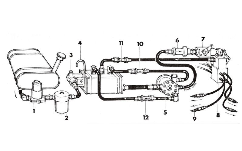
jbc426, your system is much more modern than mine. I'm using this as my implementation.

http://hilborninjection.com/mechanical-tech-support/

It's the old school way. I'm just trying to get the fuel up front where it is available for the Hilborn pump. There is no pump in my surge tank it is gravity fed through a -10 line about 6 inches long to the Hilborn pump. The Hilborn pump then provides the pressure to the injection barrel valve, The Hilborn pump bypass is routed through the primary bypass valve back to the surge tank. The tank is vented and the primary bypass has the "pill". The plumbing of mine that is different from the Hilborn diagram is that Hilborn told me not to include a "secondary" or a "hi speed" bypass. I'll try it like that to see how it works.

Really the only thing that makes them different that is your surge tank is sealed and mine is not.
Posted By: jbc426

Re: Surge Tank Implementation - 04/29/18 07:13 PM

I looked at the schematic on the Hilborn site.

If you eliminate the float bowl and just plumb the feed directly into the surge tank, convert the vent tube into the return line to the main tank and run a line from the vent to the main tank; it will work like mine does.

All other surge tank feed and return lines remain unchanged.

This will leave your surge tank full of fuel at near 0 psi and the main feed and returns on you Hilborn system unchanged.

The benefit is that your system won't be reliant on a needle and seat controlling the fuel level in your surge tank. It's one less thing to need adjustment or get hung up with a spec of dirt etc.

Attached picture surge_tank_schmatic-1.jpg
Posted By: Blucuda413

Re: Surge Tank Implementation - 04/30/18 02:05 AM

jbc426, Thanks for the review. It would appear that if I go that route there would be no need for the regulator.
© 2024 Moparts Forums