Moparts

Electrical experts please take a look. UPDATED

Posted By: Guitar Jones

Electrical experts please take a look. UPDATED - 11/14/16 04:26 PM

I have a 92 D250 CTD 2WD with the 518 auto that I've converted to lockup. I'm using a Hobbs pressure switch off the governor pressure port to activate the ground circuit for the L/U solenoid. It is tied to the O/D ground circuit so I don't get L/U unless it's in O/D. But this method leaves a little to be desired because at certain speeds I get an annoying, in and out of L/U action. Normally it's not a problem but getting caught in traffic sometimes I can't get around it without slowing down. So what I'm looking to do is find a way to activate the circuit at a higher speed or pressure and have it stay engaged until it reaches a lower speed than the activated speed. Maybe a 5 MPH difference or something. I've not been able to find a switch like this in my internet searches so if anyone has any ideas I'm all ears.
Thanks.
Posted By: Supercuda

Re: Electrical experts please take a look - 11/14/16 04:46 PM

Might need two switched plumbed in a T, one for lower pressure, one for the higher pressure. Then a relay controlled by the switches. Use the ground from the high pressure switch to the relay coil ground, This will close the relay at the higher pressure setting. Wire the lower pressure ground to a one side of a set of NO contacts on the relay, jumper the other side on that pair of contacts to the relay coil ground, this will let the low pressure switch control the opening of the relay. Remember to wire the relay coil + to a switched 12V source.

On the second set of NO contacts on the relay run a ground to one side then run the other side to activate the circuit.

How this circuit will work is like this. As the pressure rises the low side switch will make, since it is going to a set of NO contacts on the relay the signal stops there as the relay is deenergized. Pressure continues to rise until the high side switch makes, this sends a ground to the coil negative, if you remembered to wire the coil + then the relay closes. With the relay closed you now have both sets of NO contacts closed. Your circuit will energize. The ground from the low side is now applied to the relay coil - as well. At this point both the high pressure and low pressure switches are applying a ground to the relay coil -, not a problem. As pressure drops the high pressure switch will open and remove it's ground from the relay coil -, but the low side ground will still be there thru the now closed contacts. Once pressure drops enough for the low pressure switch to open the ground will be removed from the relay coil - and the relay will open removing the ground from your circuit. At this point pressure will have to rise enough to close the high pressure switch and the cycle starts over.

Short of finding an adj hi/lo switch this is how I would do it.
Posted By: Guitar Jones

Re: Electrical experts please take a look - 11/14/16 07:11 PM

Makes sense, thanks.
Posted By: RapidRobert

Re: Electrical experts please take a look - 11/14/16 07:49 PM

I still refer to your oiling mods regularly, Good job/good tech & much appreciated!
Posted By: DaytonaTurbo

Re: Electrical experts please take a look - 11/14/16 10:24 PM

Supercuda beat me to it and said exactly what I was going to describe. you are suffering from classic "chattering contact" syndrome, in which case the circuit rapidly opens/closes as you hover around the switch's pressure rating. Two switches, wired and plumbed as described will give you a usable range to work with. This is why your home air compressor shuts off at 120psi and kicks on again at 90. If it didn't that thing would running darn near all the time. If you select your second switch to be 10psi below the rating of your current switch, you will have to drop about 10mph before the OD disengages. I think you may find that 5mph difference is a little tight where a 10mph may be more reasonable, especially with a CTD.
Posted By: Guitar Jones

Re: Electrical experts please take a look - 11/14/16 10:43 PM

It's not for the O/D, it's for the L/U. I have it set to come in about 46 MPH now and I'd like it to turn off at about 40. Thanks for the help guys. More wiring fun in my future. laugh2
Posted By: BDW

Re: Electrical experts please take a look - 11/15/16 03:05 AM

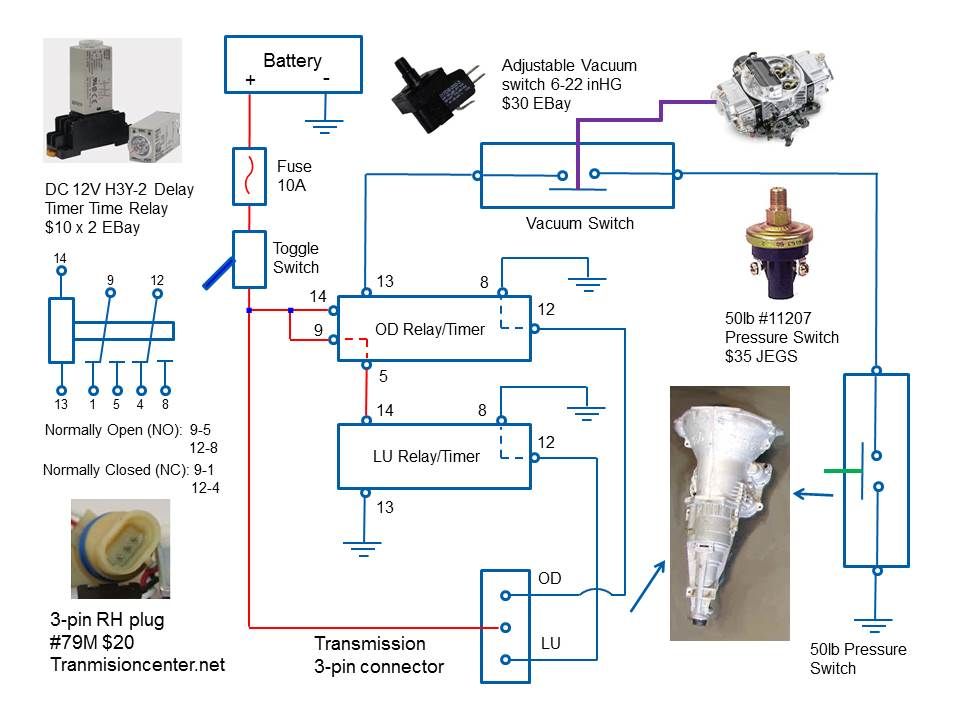
I put 2 timers in so it doesn't search, Tranny has to be in OD 10 sec or LU won't happen.

The 518 (46RH) is hydraulically controlled and uses 2 servos to enable the OD and LU.
The 3-pin connector on the transmission supplies the control voltages.
The center pin always has 12V power connected. The 2 outer pins are switched grounds. The front pin is the OD ground, the rear pin is the LU ground.

The module works according to the following sequence.
1) The 12V toggle switch supplies voltage to the relays and transmission center pin.
2) When the hydraulic pressure trips (50mph/adjustable) the pressure switch, ground is supplied to the vacuum switch. When speed is below 50mph, hydraulic switch opens, disabling OD.
3) When there is enough vacuum, the vacuum switch closes, providing the OD relay ground. Under heavy acceleration, vacuum drops, opens switch, OD is disabled.
4) When OD relay has ground and 12V, it waits 10sec, then supplies 12V to the LU relay and ground to the transmission OD pin, enabling OD.
5) Now the LU relay has 12V, it's already grounded. It waits the 10 sec programmable delay then provides ground to the transmission LU pin. So lock up doesn't occur until OD has been enabled and on for 10sec.
6) The programmable delays for both relays fix the situation when speed is fluctuating around 50mph. This would normally cause the OD to kick on/off, the 10 sec (programmable) delay stops this from happening.

Posted By: Supercuda

Re: Electrical experts please take a look - 11/15/16 03:40 AM

Good luck getting a vacuum switch to work on a diesel.
Posted By: Guitar Jones

Re: Electrical experts please take a look - 11/15/16 03:45 PM

Originally Posted By RapidRobert
I still refer to your oiling mods regularly, Good job/good tech & much appreciated!


Thanks Robert.
Posted By: Guitar Jones

Re: Electrical experts please take a look - 11/15/16 07:28 PM

Originally Posted By Supercuda
Might need two switched plumbed in a T, one for lower pressure, one for the higher pressure. Then a relay controlled by the switches. Use the ground from the high pressure switch to the relay coil ground, This will close the relay at the higher pressure setting. Wire the lower pressure ground to a one side of a set of NO contacts on the relay, jumper the other side on that pair of contacts to the relay coil ground, this will let the low pressure switch control the opening of the relay. Remember to wire the relay coil + to a switched 12V source.

On the second set of NO contacts on the relay run a ground to one side then run the other side to activate the circuit.

How this circuit will work is like this. As the pressure rises the low side switch will make, since it is going to a set of NO contacts on the relay the signal stops there as the relay is deenergized. Pressure continues to rise until the high side switch makes, this sends a ground to the coil negative, if you remembered to wire the coil + then the relay closes. With the relay closed you now have both sets of NO contacts closed. Your circuit will energize. The ground from the low side is now applied to the relay coil - as well. At this point both the high pressure and low pressure switches are applying a ground to the relay coil -, not a problem. As pressure drops the high pressure switch will open and remove it's ground from the relay coil -, but the low side ground will still be there thru the now closed contacts. Once pressure drops enough for the low pressure switch to open the ground will be removed from the relay coil - and the relay will open removing the ground from your circuit. At this point pressure will have to rise enough to close the high pressure switch and the cycle starts over.

Short of finding an adj hi/lo switch this is how I would do it.


I've been trying to sketch out this circuit but I'm missing something. If one of you guys could draw this out for me I would really appreciate it. Maybe because the solenoids have 12 volts to them key on and the circuit needs to work on the ground side that I'm getting confused.
Posted By: Supercuda

Re: Electrical experts please take a look - 11/16/16 01:30 AM

The solenoids weren't covered, just the pressure switches and the (you will need to add them) relays. I assumed the L/U and O/D solenoids always have keyed 12v to them and you switch the ground side to turn them on and off.

Attached picture relay.jpg
Posted By: Guitar Jones

Re: Electrical experts please take a look - 11/16/16 02:39 AM

Ok, so I need a double pole single throw relay. That is where I was confused trying to do it with a single pole single throw.
Posted By: Supercuda

Re: Electrical experts please take a look - 11/16/16 04:14 AM

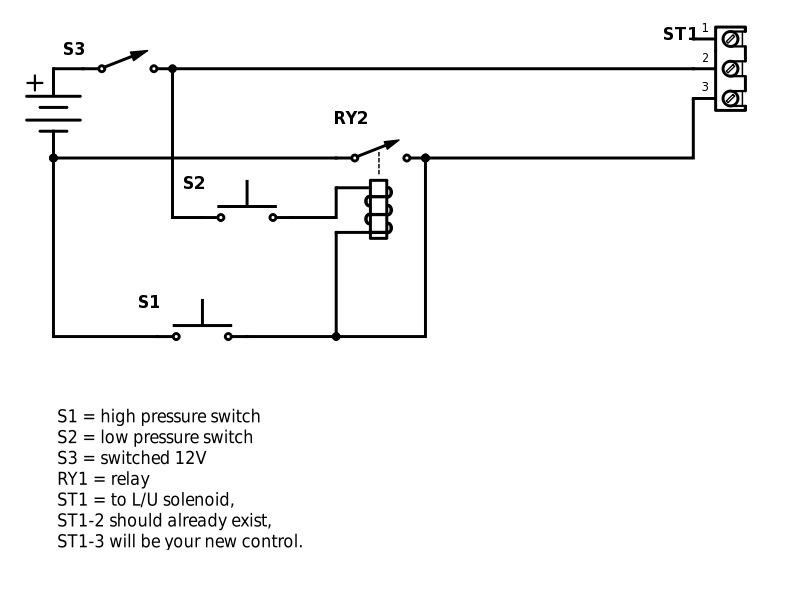
If you want a single pole I can draw that up for you. I don't like switching the positive, it's noisier in an electrical system, but obviously the OEM's do it all the time. You will note that both the coil's switched 12V and the ground now goes thru a pressure switch, different ones though. Only way I could think of to use a single pole relay without getting real complicated and expensive. Not to mention automotive grade relays are cheap and easy to find with a single pole.

Attached picture SP relay.jpg
Posted By: Guitar Jones

Re: Electrical experts please take a look - 11/16/16 04:27 AM

Originally Posted By Supercuda
If you want a single pole I can draw that up for you


But then doesn't the ground for L/U drop out when the high pressure switch opens?
Posted By: Supercuda

Re: Electrical experts please take a look - 11/16/16 04:37 AM

In this circuit, the low pressure switch (S2) makes first, supplying switched 12V to the relay (RY2) coil, no lock up at this point. As pressure continues to rise the high pressure switch (S1) makes and supplies ground to the LU solenoid and the relay (RY2) coil, energizing the relay (RY2) and the L/U solenoid. As pressure drops the high pressure switch (S1) opens, but the relay is wired to self latch on the ground side, this is the jumper from the output of the relay contacts back to the relay coil -. The low pressure switch is still energized at this point keeping switched 12V on the relay coil + and the relay stays closed and L/U engaged. Once pressure drops off enough to open the low pressure switch it removes the switched 12V from the relay coil + and the relay opens, this will also open the ground latch. L/U is now de-energised. Once pressure starts rising the cycle starts again.
Posted By: Guitar Jones

Re: Electrical experts please take a look - 11/16/16 04:55 AM

Ok, I get it now. Thanks a lot, I appreciate it.
Posted By: 6PakBee

Re: Electrical experts please take a look - 11/16/16 05:10 AM

Originally Posted By DaytonaTurbo
....This is why your home air compressor shuts off at 120psi and kicks on again at 90. If it didn't that thing would running darn near all the time. ......


DaytonaTurbo hit it with the air compressor example. If all you want is a deadband, then get a pressure switch with not only an adjustable setpoint but an adjustable deadband. Then you don't need all the space shuttle circuitry.
Posted By: Guitar Jones

Re: Electrical experts please take a look - 11/16/16 02:55 PM

Originally Posted By 6PakBee
Originally Posted By DaytonaTurbo
....This is why your home air compressor shuts off at 120psi and kicks on again at 90. If it didn't that thing would running darn near all the time. ......


DaytonaTurbo hit it with the air compressor example. If all you want is a deadband, then get a pressure switch with not only an adjustable setpoint but an adjustable deadband. Then you don't need all the space shuttle circuitry.


I know this but since there are a myriad of different switches or transducers like this I'm unable to determine exactly what I need for this application. So if you know what type of switch or transducer I need and where to get it that would be helpful. Ideally I need something that will turn on at about 65 PSI and turn off around 55-60 PSI.
Posted By: MarkZ

Re: Electrical experts please take a look - 11/16/16 09:13 PM

Originally Posted By cnxt
I put 2 timers in so it doesn't search, Tranny has to be in OD 10 sec or LU won't happen.

The 518 (46RH) is hydraulically controlled and uses 2 servos to enable the OD and LU.
The 3-pin connector on the transmission supplies the control voltages.
The center pin always has 12V power connected. The 2 outer pins are switched grounds. The front pin is the OD ground, the rear pin is the LU ground.

The module works according to the following sequence.
1) The 12V toggle switch supplies voltage to the relays and transmission center pin.
2) When the hydraulic pressure trips (50mph/adjustable) the pressure switch, ground is supplied to the vacuum switch. When speed is below 50mph, hydraulic switch opens, disabling OD.
3) When there is enough vacuum, the vacuum switch closes, providing the OD relay ground. Under heavy acceleration, vacuum drops, opens switch, OD is disabled.
4) When OD relay has ground and 12V, it waits 10sec, then supplies 12V to the LU relay and ground to the transmission OD pin, enabling OD.
5) Now the LU relay has 12V, it's already grounded. It waits the 10 sec programmable delay then provides ground to the transmission LU pin. So lock up doesn't occur until OD has been enabled and on for 10sec.
6) The programmable delays for both relays fix the situation when speed is fluctuating around 50mph. This would normally cause the OD to kick on/off, the 10 sec (programmable) delay stops this from happening.


This is a pretty slick setup, but wouldn't you run out of vacuum and fall out of OD after a certain speed? Adding another pressure switch that is rated higher that could lockout the vacuum switch could fix this.
Posted By: Supercuda

Re: Electrical experts please take a look - 11/17/16 03:12 AM

He has a diesel, a vacuum switch is not relevant to a diesel.
Posted By: 6PakBee

Re: Electrical experts please take a look - 11/17/16 03:46 AM

I'm not sure just how you have your existing switch plumbed or wired but this is one example of a pressure switch with an adjustable deadband option that looks at first glance to be suitable.

http://www.ueonline.com/bulletins/j40-b.pdf
Posted By: 383man

Re: Electrical experts please take a look - 11/18/16 08:32 PM

Looks like you guys have him fixed up with some very nice setups. This makes me remember when Mopar used a dampned pressure switch in the AC low side that controlled the comp as it would close at about 60 psi in the system and open about 28psi. This is good info you all helped him with. Ron
Posted By: Guitar Jones

Re: Electrical experts please take a look - 12/19/16 01:20 AM

Yes they did Ron. I used Supercuda's second schematic, thank you again, but I added a second relay for the PCM ground and ran the grounds for both solenoids and the lockup relay to the second relay then used the original O/D ground to the PCM to trigger the second relay.

I did this for a couple reasons.

1.) So I don't get L/U until the trans is in O/D

2.) If you use a separate circuit for L/U the trans will not down shift once it is in L/U. Not good when you need to accelerate at 45 MPH and you are in O/D and L/U.

3.) I didn't want to chance burning out the driver in the PCM running three circuits through it. They aren't exactly available everywhere.

So it now works great, I get L/U at 44 MPH and it unlocks at 37 MPH. Almost like the truck came from the factory that way. If I didn't have the PCM controlled O/D I would have had to do something more complex but as it is now it's perfect. Thanks again!!
© 2024 Moparts Forums