Moparts

need Challenger wiring harness schematic

Posted By: moparmikethree

need Challenger wiring harness schematic - 06/18/14 03:24 AM

I want to redo my wiring harness (engine) because it is the original wiring that was tied in for electronic ignition.. Here is what i'm working with. a lot of the wiring is cracked

70 Challenger, 360 engine, automatic, electronic ignition
do in need to put in the ballast resistor? currently it is a dual post.
could someone post a schematic or tell me where to look. If i ordered a new on should it be for a 72 Challenger because of the electronic ignition. is there anything on this forum

Thanks
Posted By: RapidRobert

Re: need Challenger wiring harness schematic - 06/18/14 03:44 AM

IF the only difference between the '70 and the '72 harnesses is that the '72 has the extra circuits for the electronic ign & you stated you have added electronic ign then yes I would get a '72 harness. I'm assuming you are using a chrome or orange or some other ECU that is a 4 pinner? If so plug in a 2 terminal "single" ballast that has the ohms you desire to match your coil on the ballast white connector side that has the brown wire on one end, and another 2 terminal "single" ballast side by side of any ohms as it is just there to fill the harness for appearances' sake and it goes nowhere on a 4 pin ECU or a replacement parts house 5 pin which has a dummy 5th pin. Only the factory OE 5 pin ECU's have a functioning 5th pin & REQUIRE a 4 terminal "dual" ballast setup.
Posted By: Ron_M

Re: need Challenger wiring harness schematic - 06/18/14 03:44 AM

Wiring Diagrams

http://www.mymopar.com/index.php?pid=28

Here's some Dodge Service Manuals for quick reference:

http://www.mymopar.com/index.php?pid=109
Posted By: Steve Bryant

Re: need Challenger wiring harness schematic - 06/18/14 01:45 PM

So I have a 1970 Barracuda and my original wiring had the normal "single" ballast and no support for ECU. I ordered the new engine wiring harness from YearOne, I specified electronic ignition and so it came with double-ballast connectors and support for the ECU.

I did not have to do anything extra except buy a double resister and it works excellent!

Also, I took the online wiring images for our car and used some tools to clean them up and glue them together. I think the .PDF files are too big to post so if you PM me your email address I will email the PDF to you. I have a plotter at home and so when I am working on my car I print them poster-sized and it helps me when I am under the hood. I have a few other wiring images I have collected as well that may help. PM me and I will get these all to you.
Posted By: Steve Bryant

Re: need Challenger wiring harness schematic - 06/18/14 05:38 PM

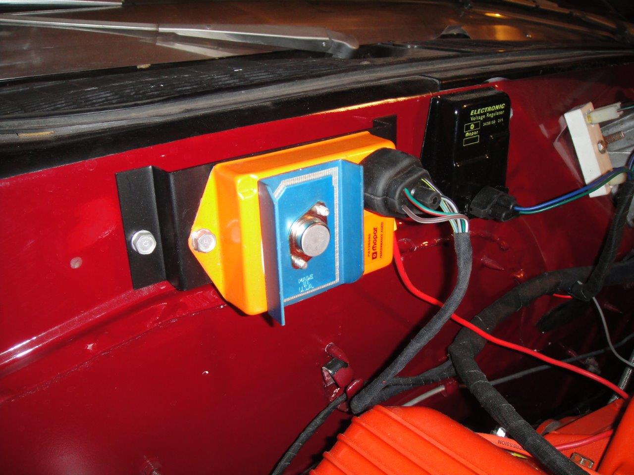
The YearOne harness looked pretty good in my opinion, but I wrapped mine in friction tape to make it look a little better and to clean it up a little.

As you can see I added an ECU bracket which is typical in later years and I tried to use a double ballast where the single used to go. It does not fit as well as I would like but I haven't found a way I like better yet.

I did not choose the double-ballast but when I ordered the '70 Cuda engine harness for a 440 and Electronic ignition, this is what they sent me. I can post any photo you want of the harness and its connections. I did make some modifications for electric choke, horn wiring and MAD bypass wire but with a little friction tape it all looks factory.

Attached picture 8179955-wiring.jpg
Posted By: RapidRobert

Re: need Challenger wiring harness schematic - 06/18/14 09:55 PM

Quote:

I tried to use a double ballast where the single used to go. It does not fit as well as I would like but I haven't found a way I like better yet.


an option would be to cut off the (2) white "dual" ballast connectors & solder in (2) 1/4" female connectors (A & B) on respectively (A) the brown wire end (corner) which has the ign2 (crank) wire from the ign sw & the brown wire that goes to the coil positive primary and (B) the blue wire (on the other end but on that same side) which is the ign1 (run) coming from the ign sw plus solder/crimp on the blue/yellow wire that was on the other end of the blue loop (which is catecorner from the brown wire) cuz that feeds the ECU & plug A and B terminals into a 2 terminal "single" ballast then tape up the now unused wire on the other side that goes to the unused red/green wire/pin in the pentastar ECU connector for neatness. This will also allow you to run a hotter ballast as the one for the coil half on the 4 terminal "dual" ballast has alot of ohms (which actually that much ohms might not be a bad idea considering the color of your box )
Posted By: Steve Bryant

Re: need Challenger wiring harness schematic - 06/18/14 10:46 PM

Robert,

I like the idea alot but I will circle back on that. Right now I am working on my seats!

-Steve
Posted By: BDW

Re: need Challenger wiring harness schematic - 06/18/14 11:20 PM

What's the difference between 4 and 2 wire ballast. When did that change?

Wondering if a 71 or 72 engine harness would be a better choice for a 70 340?

Too bad there's not a chart with all the differences, I would have thought all 70-74 were the same.
Posted By: Steve Bryant

Re: need Challenger wiring harness schematic - 06/19/14 12:51 AM

In flipping through my "Original Challenger and Barracuda 1970-1974" book the photos with ECU's look to have double ballasts. Those would be from years 1971-1974. If you look closely, the photos without ECU's show a single ballast. I even saw a '74 with a single ballast and no visible ECU. There are a couple of pictures where you can't quite see everything but overall that book would suggest that the double ballast was perhaps tied in some way to Electronic Ignition (for some cars at least.)

I know that book is not the ultimate authority and a table from Mopar would be far better but I suspect that Electronic ignition (from 1971-1974) had at least some bearing on the ballast used.
Posted By: 71_deputy

Re: need Challenger wiring harness schematic - 06/19/14 01:11 AM

4 pin ecu used single ballast for the coil- ecu had full line voltage- if voltage surges- could pop the transistor/heatup.

dual ballast- same resistance on first ballast for coil--- second was for lowering the voltage to the ecu- hence- 5 pin.

you could use a 4 pin ecu in a 5 pin/dual ballast setup- but not a 5 pin to a 4 pin harness setup.
© 2024 Moparts Forums