|
 Re: Wire guage
[Re: 70duster340]
#618703
Re: Wire guage
[Re: 70duster340]
#618703
03/04/10 05:52 PM
03/04/10 05:52 PM
|
Joined: Aug 2007
Posts: 6,095
Valencia, España
NachoRT74

master
|
master
Joined: Aug 2007
Posts: 6,095
Valencia, España
|
Initially I like your idea... and maybe in fact myself will make it on that way.
however ONCE I got a short from blue line ( I didn't know about my car electric on those days yet ), when the alt brush isolator got broken and all the blue line began to heat up to ign switch, melting slightly a couple of plugs, so thinking on that, is not a bad idea get it fuse protected like painless sugestion.
The fuse for the dimmer line.... mmmm I don't think is EXCESIVELLY necesary and splice tan and orange together will work. Is already protected by the pink input line. Just that if some short at dimmer circuit, will blow at the same time with parking lights. A smaller fuse on dimmer circuit will blow the dimmer fuse first keeping safe the parking circuit.
Now... what circuit is more important to keep it fused ? which one is easier to get a short ?... make your choice
I think on this, is about a personal preference for each one
With a Charger born in Chrysler assembly plant in Valencia, Venezuela
|
|
|
Re: Wire guage
[Re: NachoRT74]
#618704
03/04/10 06:02 PM
03/04/10 06:02 PM
|
Joined: Aug 2007
Posts: 6,095
Valencia, España
NachoRT74
master
|
master
Joined: Aug 2007
Posts: 6,095
Valencia, España
|
I GOT AN IDEA!!!
Do you find some way to separate the ELC FAN or the ALT/REG fuses from the Acc buss bars ? cut/separate the bar from fuses at those points ? AND still able to attach the tan wire on the cut/separated point from the Acc bar ?
you could use one of those fuses to feed some separated option from buss bars.
DASH INSTRUMENT source... you can splice the blue wire to cluster master plug into the pink wire going to ballast to keep it working when cranking as originally did
you can try also separate this DASH INSTRUMENT fuse from the acc buss bar and feed it from the blue line before the fuse box to make it work also when cranking, like originally is.
How are the fuses attached to buss bars ? can you give me a close up pic of that ? I can't detail that on pics you sent me
With a Charger born in Chrysler assembly plant in Valencia, Venezuela
|
|
|
Re: Wire guage
[Re: 70duster340]
#618706
03/05/10 01:13 AM
03/05/10 01:13 AM
|
Joined: Aug 2007
Posts: 6,095
Valencia, España
NachoRT74
master
|
master
Joined: Aug 2007
Posts: 6,095
Valencia, España
|
first... which red wire ? the main system power from painless ? that wire doesn't run to the bulkhead, will run to the ammeter ( black side ) to keep it working. after clearing that... MMMMMM Reeally really, no need for the stock 12 gauge replacement if you already will run the parallel wires. IMHO keep that one on the way it is, and run the parallel ones on 10 gauge. If you want to be able to keep "serviceable" all the circuit including the new ones through the firewall, the new parallel wires can be plugged with the bullet kind ones on engine bay side. They are available for 10 gauge, the ones with yellow covers ( I think those are what supports 10 gauge ). Since I don't like the colored look of those plastic covers I normally cover them up with black ( or wire matched color )shrinking tube NOTE... even terminals can it be simply crimped, I normally also SOLD THEM. That gives you better power transference and harder to loose from terminal. In fact as far is posible, SOLD EVERY SPLICE... don't simply twist them together you can tin the ends before twist them but you can tin them after being twisted too with the propper heat range solder, specially big gauge ones. Small gauge wires can be tined either way after or before.       wrong way:  maybe you already did know this, but never is wrong to give more info just in case
|
|
|
 Re: Wire guage
[Re: NachoRT74]
#618707
Re: Wire guage
[Re: NachoRT74]
#618707
03/05/10 01:34 AM
03/05/10 01:34 AM
|
Joined: Jan 2003
Posts: 1,443
70duster340
OP
pro stock
|
OP
pro stock
Joined: Jan 2003
Posts: 1,443
|
Yes, that was the red wire I was speaking of. So, if I run the parellel wires, do they get attached to the ammeter? If so, how? And, which gauge of fusible link do I need to connect to the starter relay for the parellel wires?
Also, as it is currently set up, the red wire does run from the bulkhead to the fuse block. I don't have the dash installed yet, so it's not attached to the ammeter. Right now the red wire comes from the bulkhead connector and feeds the fuse block.
Last edited by 70duster340; 03/05/10 01:40 AM.
|
|
|
Re: Wire guage
[Re: 70duster340]
#618708
03/05/10 08:49 AM
03/05/10 08:49 AM
|
Joined: Jan 2003
Posts: 1,443
70duster340
OP
pro stock
|
OP
pro stock
Joined: Jan 2003
Posts: 1,443
|
|
|
|
Re: Wire guage
[Re: 70duster340]
#618710
03/06/10 06:13 PM
03/06/10 06:13 PM
|
Joined: Aug 2007
Posts: 6,095
Valencia, España
NachoRT74
master
|
master
Joined: Aug 2007
Posts: 6,095
Valencia, España
|
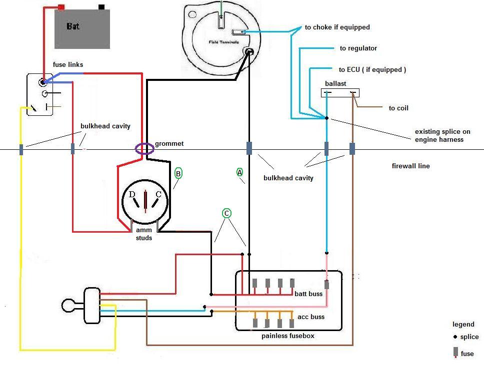
Ok here is the diagram with the parallel wires on it and the main circuits ( I simply edited the one I already had made )
as you can see I'm posting wich wires will still run throught the bulkhead plug. Honestly no need to eliminate them, but some service on them will be nice ( clean, new terminals if wished, dielectric grease )
the parallel wires will still run up to ammeter studs... why? because when you run the parallel wires, the black wire from ammeter to fuse box won't necesarilly feeds the power from batt, through ammeter, now will feed the power from alternator too ( as far alternator is enough of course ) because so that will DOUBLE the direct and original wire coming from alt through bulkhead.
So we can say ORIGINAL we had one wire ( labeled A ) what it was the only one feeding the main splice originally, now directly the fuse box bar.
The added B wire through the firewall, attached to ammeter, will make we are getting two wires now LABELED AS C to feed the fusebox buss bar from alt . Once again as far alt is enough. If alt is not enough, then batt will feed through ammeter. Ammeter will tell you when that happens, thats its function.
8 or 10 gauge... 10 is really enough if you ask me and will find terminals for it at hardware stores. I fit 8 gauge just because it was one one I had handly from a Coronet 77, but that made me imposible to find a terminal to fit on engine bay side to be able to service that because there is not 8 gauge terminals.
Batt side parallel wire I used a 10 gauge and fit a terminal to attach to a new fuse link. ( 14 or 16 gauge ). The original fuse link it is 16 gauge. Mopar wirings showing parallel wires shows 14 gauge for that parallel fuse link, but 16 will work too without problems. At the end yoiu are also doubling the fuse link, and use a 14 gauge will take too much time to blow in a short problem.
why use a 10 gauge wires if still stock wires betwen ammeter and fuse box and alt and fuse box are 12 ? because teh extra gauge step is for BATT CHARGING moment, safer, not really because the regular car equippment requires MOOORE thicker wires. You are not driving a Motorhome, is a regular passenger car.
Will you use an UZI to hunt rabbits ? everything on the right and enough measure. No need to oversize stuff
With a Charger born in Chrysler assembly plant in Valencia, Venezuela
|
|
|
Re: Wire guage
[Re: 70duster340]
#618712
03/07/10 01:14 AM
03/07/10 01:14 AM
|
Joined: Aug 2007
Posts: 6,095
Valencia, España
NachoRT74
master
|
master
Joined: Aug 2007
Posts: 6,095
Valencia, España
|
remember the fuse box is on painless box becoming on the original MAIN SPLICE.
The MAIN SPLICE needs to keep on alt side of ammeter to keep the right reading
the instruction sheet on painless box says attachs the batt wire on the red 12 gauge fusebox wire just because they are not thinking on an ammeter on the line
So keeping the original wiring, the batt wire will still keep running directly to ammeter.
THEN FROM AMMETER ( black wire ) to the painless fuse box 12 red wire. ( main power source )
The ammeter is simply an IN LINE DEVICE coming from batt, what reads the batt power status.
Imagine the ammeter doesn exist... well you are making the same than instruction sheet says, you are feeding the fuse box from batt... but on this case with an ammeter in the line ( serial conection ).
remember BE SURE hook the right wires at ammeter. The BATT ones at the stud labelled RED on back of cluster, and the black wire at the normally unlabeled stud.
If you hook reversed, won't happen anything more than simply a reversed reading on ammeter
extra note:
remember on stock setup the black traced white wire to headlights switch wire is spliced at the main splice ( alt side ). You can splice it at the main system source ( painless red 12 gauge wire ) or directly to the black stud at ammeter. Will be easier to you hook it with eyelet terminal directly to the ammeter black side stud and will give you a less stressed wire on that section ( section between ammeter and painless fuse box )
If you hook the headlighst wire to the ammeter studs will have 2 wires on red ( original and parallel ) and will have 3 to the black side ( original now running to painless box, parallel and headlights wires )
BE SURE CLEAN the terminals arriving to ammeter AND TIGHT the ammeter nuts to be sure about a good power transfer. Lot of problems use to begin there.
Dunno what you decided to do with the horn relays, using the original or the one with painless box... and still keep the ign key in buzzer. If you decided to keep the original full relay function or if just use the buzzer function of it, the Violet wire of the original relay it must be constantly feeded. As the valiant diagram shows, normally is spliced at the MAIN original splice, so you could run that wire also to ammeter black stud, to the MAIN SYSTEM red wire at painles wire splice or also to any BATT source at fuse box after the fuses.
dunno what else to refresh right now
Dunno what you decided to do with the DASH INSTRUMENT source, from acc side of box
With a Charger born in Chrysler assembly plant in Valencia, Venezuela
|
|
|
Re: Wire guage
[Re: NachoRT74]
#618713
03/07/10 09:20 AM
03/07/10 09:20 AM
|
Joined: Jan 2003
Posts: 1,443
70duster340
OP
pro stock
|
OP
pro stock
Joined: Jan 2003
Posts: 1,443
|
Right now I have the headlight wire attached to the terminal for power to the headlight switch (#12 on instructions). As for the instrument feed, I haven't changed that yet, but was going to. That terminal is fed by a 10 amp fuse. Should I change that, or leave it as is? The horn relay, I used the Painless one, but would very much like to keep the buzzer. So, I need to keep the violet wire hot? Also, what about the black wire from the instrument panel? From the 1970 Plymouth Valiant wiring diagram, this wire feeds the electricity to the printed circuit connector, which (I believe) feeds the voltage regulator for the instruments. On the rallye cluster, the voltage regulator is built into the fuel gauge. Does this wire need to be attached to the fuse block at the dash B+ terminal (#11 on the instructions)? I know, lots of work on your part. But, I don't think I could make this work without your assistance, so I hope you don't mind all these questions!!! 
|
|
|
Re: Wire guage
[Re: 70duster340]
#618714
03/07/10 05:46 PM
03/07/10 05:46 PM
|
Joined: Aug 2007
Posts: 6,095
Valencia, España
NachoRT74
master
|
master
Joined: Aug 2007
Posts: 6,095
Valencia, España
|
no I don't mind all the questions. thats why we are around and boards intention. headlight wires... Remember Mopars have two diff sources for headlight switch ( pink and black traced white ). Painless is Chebby based so thats teh reason they give just one source for it. I guess if you hook the black traced white wire in to the point 12 at instructions, you spliced the pink wire there too, right ? If you ask me I would preffer to keep the original setup with two diff input sources. Just my personal preference. If your fuse blows out because some fail on parking lights feeded by the pink wire, will be out of headlights too because the black traced white is spliced there too. Dash instrument fuse... 10 amps, is not bad but maybe I will feed with 8 amps. Black wire for instrument panel ? Valiant diagram shows a blue one not a black one. Dunno if standart or rallye makes diff on wire color alos for A bodies. It does on B bodies, but dunno on A bodies. Is a fact the DASH WIRE on painless fusebox must arrive to the voltage limiter because voltage limiter is the source for the gauges. But Painless DASH WIRE must feed also the idiot lights ( normally blue wire on stock ), but not through the voltage limiter. Idiot lights must be directly feeded from the positive source. On B bodies with rallye cluster, gauges are feeded with a black wire from ACC directly to the voltage limiter for a while Brake light is a blue wire directly from RUN. On Standart Cluster all dash ( gauges AND idiot lights ) is feeded by the blue wire from RUN circuit with voltage limiter instered in to the blue wire circuit at printed board. Maybe A bodies are the same ?  I guess because Mymopar website doesn't show any rallye diagram Buzzer. yes, will need to keep the violet wire hot.
With a Charger born in Chrysler assembly plant in Valencia, Venezuela
|
|
|
Re: Wire guage
[Re: NachoRT74]
#618715
03/07/10 06:52 PM
03/07/10 06:52 PM
|
Joined: Jan 2003
Posts: 1,443
70duster340
OP
pro stock
|
OP
pro stock
Joined: Jan 2003
Posts: 1,443
|
About the light switch, yes I did splice both the pick and the black w/white tracer together and attached them at the light switch terminal. I didn't know where else to draw any electricity from for both wires individually. On my rallye dash, the blue wire feeds the brake light, and the black wire feeds power to the voltage limiter. The gauge layout may be different from a B-body to an A-body, I don't know for sure. I can say that an early Barracuda rallye dash layout is different from mine. I also could not locate a rallye dash wiring diagram, and have posted on here as well as mymopars, but with no luck so far. I do have a copy of the printed circuit boards for the Duster/Valiant (and others too), which has helped a lot. Do you need me to give you a rundown of the terminals and what I have connected to each one, maybe for one last check before we finally finish this? 
|
|
|
Re: Wire guage
[Re: 70duster340]
#618716
03/07/10 08:02 PM
03/07/10 08:02 PM
|
Joined: Aug 2007
Posts: 6,095
Valencia, España
NachoRT74
master
|
master
Joined: Aug 2007
Posts: 6,095
Valencia, España
|
yeah well your rallye wiring is the same than my rallye wiring... yes the black wire to voltage limiter will be spliced in to the DASH INST wire of painless box.
Blue wire for brake light. To make it CORRECTLY into a Mopar way, must be spliced into the blue RUN circuit. Now, mostly sure you never touched that though. That will set correctly that when you crank the engine, the brake light will remaing lighted up ( but dimmed )
On a standart cluster as stated, is being set diff just by one wire to feed everything ( blue ) and to set correctly the painless box in a Mopar would need to modify some stuff more. I based my suggestion about the dash feed mods ( cut the buss bar or whatever related ) on the Standart cluster diagram. No need it on this case now.
to draw both lights wires, splice the black traced into the ammeter black wire stud OR the MAIN SYSTEM SOURCE. as you wish. I think easier directly to amm stud. Keep the pink into the fuse box provision. Well thats my suggestion to make it on the Mopar way. Both spliced into the Fusebox provision will work too though but when the fuse blows, you will be OUT OF LIGHTS EVERYWHERE. It happened to mee that I blowed that fuse simply replacing the glove box bulb ( didn't unplugged batt ) because on my car, this bulb comes from same source. Dunno remmeber on your car. Will have to check. I could get without headlights just for that if they were on same source.
a rundown will be nice.
With a Charger born in Chrysler assembly plant in Valencia, Venezuela
|
|
|
Re: Wire guage
[Re: NachoRT74]
#618717
03/07/10 10:24 PM
03/07/10 10:24 PM
|
Joined: Jan 2003
Posts: 1,443
70duster340
OP
pro stock
|
OP
pro stock
Joined: Jan 2003
Posts: 1,443
|
OK, here it is: Battery feed side, from left to right: Horn terminal - green w/red tracer Ign sw coil - dark blue w/white tracer from ballast Batt feed - empty Ign sw B+ - red wire from ignition switch Stop sw B+ - pink wire to brake switch Alt batt post - black wire from alternator Haz sw B+ - pink wire to directional signal plug Light sw B+ - black w/white tracer and pink, both to headlight switch plug Dash B+ - black wire to voltage limiter in cluster plug Radio B+ - to radio plug Acc side, from left to right: Horn sw - black w/white tracer to directional switch plug Wiper B+ - to wiper plug Coil/Dist - dark blue w/white tracer out to ballast Dome light B+ - to plug for rear harness El fan B+ - empty AC/Heat - black w/white tracer out to fan controls Alt ign B+ - empty Ign sw accy - black from ignition switch plug Turn sw B+ - red w/white tracer o directional switch plug I'm sure I have some of these incorrect, so please advise your opinion so I can make the proper changes. I think that I may have the ballast wires incorrect, and I will also change the power to the light switch as you had previously suggested. Thanks!!! 
|
|
|
Re: Wire guage
[Re: 70duster340]
#618718
03/08/10 10:14 AM
03/08/10 10:14 AM
|
Joined: Aug 2007
Posts: 6,095
Valencia, España
NachoRT74
master
|
master
Joined: Aug 2007
Posts: 6,095
Valencia, España
|
Caps, my notes: Quote:
Battery feed side, from left to right:
Horn terminal - green w/red tracer---- YES, RUNNING TO BULKHEAD
Ign sw coil - dark blue w/white tracer from ballast---- WELL I GUESS IS REALLY THE ONE COMING FROM IGN SWITCH
Batt feed - empty ---- THE ONE ( BLACK )COMING FROM AMMETER
Ign sw B+ - red wire from ignition switch--- YES
Stop sw B+ - pink wire to brake switch--- YES
Alt batt post - black wire from alternator--- YES
Haz sw B+ - pink wire to directional signal plug--- YES
Light sw B+ - black w/white tracer and pink, both to headlight switch plug--- YES SOMEHOW. MY PREFFERENCE IS SPLICE THE BLACK ONE ON A DIFF POSITIVE SOURCE BETWEEN AMMETER AND FUSEBOX MAIN SOURCE. JUST MY PREFFERENCE LIKE MOPAR DID. BUT WILL WORK.
Dash B+ - black wire to voltage limiter in cluster plug--- YES
Radio B+ - to radio plug--- YES.
Acc side, from left to right:
Horn sw - black w/white tracer to directional switch plug--- I CAN'T RECALL BEING TRACED, BUT YES, BLACK COMING FROM DIRECTIONAL SWITCH
Wiper B+ - to wiper plug--- YES, PINK ONE
Coil/Dist - dark blue w/white tracer out to ballast--- YES
Dome light B+ - to plug for rear harness--- YES, PINK ONE
El fan B+ - empty--- I GUESS LOL
AC/Heat - black w/white tracer out to fan controls--- YES. I GUESS YOU HAVE HEATER, NON AC
Alt ign B+ - empty--- YES
Ign sw accy - black from ignition switch plug--- YES
Turn sw B+ - red w/white tracer to directional switch plug--- I CAN'T REMEMBER TRACED IT, BUT YES
I'm sure I have some of these incorrect, so please advise your opinion so I can make the proper changes. I think that I may have the ballast wires incorrect, and I will also change the power to the light switch as you had previously suggested.
Thanks!!!
I thought you where to use the coil fuse for the dimmered cluster source instead ( tan and orange )... whatever, you set it right for the original use. If you decide to use for dimmer, will be fine too.
then beside everything of this remmeber after make some cuts you could it be cutting some power sources like cigar lighter, glove box... These must be sourced on any constant power source at batt side. You can have also some BATT source around hanging around on underdash harness. This source is a rubber plug with 3 female bullet terminals color red. You can splice these into the hazzards or brake fuses section. Normally in fact the glove box is plugged into the BATT rubber plug I was talking about hanging around.
Key In Buzzer... violet wire also allways hot. It Can be fused or not. Like the cigar lighter or glove box lights, OR like originally factory did, between ammeter and MAIN POWER SOURCE
I guess the blue wire to brake light is still attached to the RUN circuit. If you did cut it, you can splice it after the fuse to coil. That will tell you if fuse did blow or not.
I guess you rid off both flashers around and related wires.
BE SURE THE BATT, AMMETER, ALT AND IGN SPLICES ARE GOOD MADE!!! These runs ALL the car load
With a Charger born in Chrysler assembly plant in Valencia, Venezuela
|
|
|
Re: Wire guage
[Re: NachoRT74]
#618719
03/08/10 12:31 PM
03/08/10 12:31 PM
|
Joined: Jan 2003
Posts: 1,443
70duster340
OP
pro stock
|
OP
pro stock
Joined: Jan 2003
Posts: 1,443
|
OK, as it is right now I have the red 12 gauge wire that comes from the starter relay straight to the fuse block from the bulkhead connector,connected to the batt feed terminal. Can I just cut that wire and splice in the ammeter? I also will run the parallel wires to the ammeter.
You are correct, it is a heater only car, no AC.
I will attach the power wire for the headlights (black w/white tracer) to the black side of the ammeter, as you suggested.
The dimmer for the lights, I will connect the tan and the 2 orange wires together, and splice in a fuse. I would rather use the fuse for the coil, as directed in the instructions.
|
|
|
Re: Wire guage
[Re: 70duster340]
#618720
03/08/10 03:45 PM
03/08/10 03:45 PM
|
Joined: Aug 2007
Posts: 6,095
Valencia, España
NachoRT74
master
|
master
Joined: Aug 2007
Posts: 6,095
Valencia, España
|
Quote:
OK, as it is right now I have the red 12 gauge wire that comes from the starter relay straight to the fuse block from the bulkhead connector,connected to the batt feed terminal. Can I just cut that wire and splice in the ammeter? I also will run the parallel wires to the ammeter.
on the way you did, you were bypassing the ammeter
to keep working ammeter, it must be in the middle of the line of the starter relay wire ( batt ) and the MAIN POWER SYSTEM wire at fusebox
be sure all the eyelet terminals to ammeter good crimped AND welded. I would cover this crimping/weldin section at terminal also with shrinking tube. Two of them to extra isolation
of course, nuts propperly tightem up.
With a Charger born in Chrysler assembly plant in Valencia, Venezuela
|
|
|
|
|


